
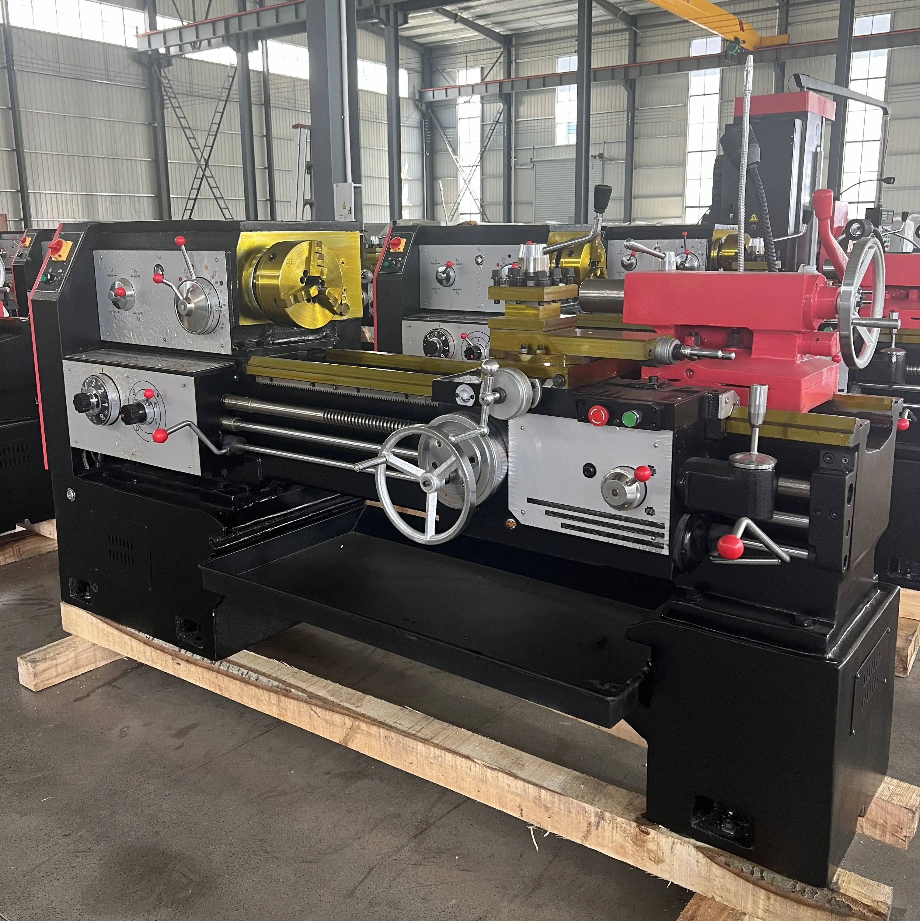
1. Why CA6140 and CA6150 remain relevant to B2B buyers
A general-purpose horizontal lathe is still a core asset for repair shops, maintenance departments, vocational workshops, and small-to-mid-sized production lines. The CA6140 and CA6150 family is designed around a familiar turning workflow: the workpiece is held by the spindle, the tool post travels along or across the bed, and the operator selects spindle speed and feed according to the material and operation.
For procurement managers, the value is not a promise of one universal output rate. The value is a clear mechanical envelope that can be checked before purchase. The queue specification identifies a maximum swing over bed of 400 mm, a maximum workpiece length of 1000 mm, a 52 mm spindle bore, and a 205 mm distance from spindle center to the bed-plane guide rail. These figures give the buyer a practical starting point for checking shaft diameter, chuck clearance, bar stock, and fixture access.
This guide is intended for B2B sourcing decisions. It separates the supplied machine data from items that must be confirmed for a specific quotation, such as motor power, overall dimensions, machine weight, chuck configuration, electrical standard, tooling package, and delivery terms. Those variables should not be assumed from the model name alone.
2. Reading the supplied technical envelope
The first procurement question is whether the lathe can physically accept the workpiece. A 400 mm maximum swing over bed is the headline clearance figure, but it is not the same as the maximum turning diameter for every setup. The carriage, tool holder, chuck jaws, tailstock, and selected cutting tool can reduce the usable envelope. Buyers should send a drawing or sample dimensions to the supplier and request a setup-specific confirmation.
The listed maximum workpiece length is 1000 mm. In practice, the usable length depends on how the work is supported. A short part held in a chuck may leave room for a tailstock or steady-rest arrangement, while a long slender shaft may require additional support to control deflection. The correct buying decision therefore combines the 1000 mm listed length with the actual part geometry, clamping method, and required surface finish.
The 52 mm spindle bore is particularly relevant to maintenance workshops and shaft-processing buyers. It helps determine whether bar stock or an existing shaft can pass through the spindle rather than being limited to work held only in front of the chuck. Confirm the actual chuck, spindle nose, and bar-feeding arrangement in the commercial offer before treating the bore as a complete bar-capacity specification.
| Buyer question | Supplied reference | What to confirm before order |
|---|---|---|
| Can the part clear the bed? | Max. swing over bed: 400 mm | Actual turning diameter with chuck, tool and carriage |
| Can the part fit lengthwise? | Max. workpiece length: 1000 mm | Support method, tailstock reach and part drawing |
| Can bar stock pass through? | Spindle bore: 52 mm | Spindle nose, chuck and bar-work arrangement |
| Can the tool reach the work? | Upper tool holder stroke: 140 mm | Tool holder, compound position and required approach |
3. Spindle selection: speed range and workholding discipline
The supplied data lists 24 forward spindle speeds and 12 reverse speeds. The forward range is 10-1400 r/min, while the reverse range is 12.5-1400 r/min. This broad range gives the operator room to match spindle speed to workpiece diameter, tool material, cutting operation, and surface-finish target. It does not remove the need for cutting-data validation; the correct speed still depends on the material and tool geometry.
Low-speed capability is useful when a large-diameter workpiece, threading operation, or controlled roughing pass requires higher torque at the spindle. The upper end of 1400 r/min can support smaller diameters and finishing work when the workholding, tooling, balance, and machine condition are suitable. Buyers should ask whether the quoted configuration includes the same speed table, transmission arrangement, and electrical frequency required for the destination market.
Reverse rotation can support selected operations such as backing out a tool or cutting with a suitable setup, but it must never be treated as a substitute for safe workholding. The chuck key, jaw condition, part projection, and tool clearance remain operator-controlled risks. Include safety training, guarding, emergency-stop configuration, and operating instructions in the acceptance checklist.
4. Feed ranges and how they affect production planning
The CA6140/CA6150 data lists 64 longitudinal feed kinds and 64 cross-traverse feed kinds. The longitudinal normal feed range is 0.08-1.59 mm/rev, the fine range is 0.028-0.054 mm/rev, and the coarse range is 1.71-6.33 mm/rev. The cross-traverse normal range is 0.04-0.79 mm/rev, the fine range is 0.014-0.027 mm/rev, and the coarse range is 0.86-3.16 mm/rev.
These ranges should be read as process-control options rather than as a guaranteed cycle time. A roughing operation may require a different feed strategy from a finishing pass. Tool nose radius, material hardness, depth of cut, coolant practice, rigidity, and operator experience all influence the result. During a supplier trial, ask for a documented sample process with the same material and drawing used by your workshop.
The distinction between normal, fine, and coarse feed is useful when building a production plan. Fine feed can support controlled finishing or delicate work, while coarse feed can help remove material more quickly when the machine, tool, and workholding are appropriate. The buyer should evaluate the complete feed table together with threading capability, change-gear or gearbox configuration, and the actual operating procedure supplied with the machine.
5. Tool-post travel, setup time, and operator workflow
The listed longitudinal rapid movement speed of the tool post is 4 m/min, and the rapid traverse speed of the tool post is 2 m/min. These figures are useful for estimating setup and repositioning behavior, but they should not be confused with cutting speed. Rapid movement normally takes place away from the cut and must be controlled so that the tool, chuck, tailstock, and workpiece remain clear.
The upper tool holder has a maximum stroke of 140 mm. When checking a part drawing, confirm not only the required tool movement but also the compound-slide angle, tool-holder height, insert or HSS tool dimensions, and access to shoulders or recesses. A practical factory acceptance test should include facing, outside turning, a shoulder, a boring or internal operation if required, and a thread or feed demonstration where applicable.
For procurement, setup time is often as important as nominal spindle speed. Prepare a tooling list before ordering: chuck type, tool holders, boring bars, centers, steady rest, faceplate, thread gauges, and measuring instruments. If an item is not explicitly included in the quotation, record it as an optional accessory rather than assuming it is part of the standard package.
6. Mechanical inspection checklist for receiving teams
Before signing final acceptance, the receiving team should compare the delivered nameplate and machine configuration with the purchase order. Verify the CA6140 or CA6150 model designation, electrical rating, spindle direction, speed selection, feed selection, and included accessories. Photograph the machine condition and record any transport damage before installation.
Check bed and carriage movement across the working travel. The movement should be smooth and free from abnormal binding. Inspect the spindle, chuck mounting, tailstock alignment, cross slide, compound slide, leadscrew, feed rod, lubrication points, guards, and emergency-stop function. The supplied product record does not state a runout tolerance or geometric accuracy value, so those values should come from the supplier's inspection report or the agreed acceptance standard, not from an assumption.
A buyer should also confirm foundation requirements, lifting points, installation clearance, coolant or chip-management provisions, and access for routine maintenance. If the lathe is intended for a production cell, document the interface with material storage, inspection equipment, and downstream marking or labeling. This turns a machine purchase into a repeatable process rather than an isolated equipment delivery.
- Verify model and serial information against the purchase order.
- Confirm the 400 mm swing, 1000 mm listed workpiece length, and 52 mm spindle bore against the agreed configuration.
- Test forward and reverse spindle selection across the supplied speed table.
- Test longitudinal and cross feed selection in normal, fine, and coarse ranges.
- Inspect tool-post rapid movement, upper holder stroke, guards, lubrication, and emergency stop.
- Run a sample part using the buyer's material and record measurements before final acceptance.
7. Questions to include in an RFQ for CA6140 or CA6150
A clear RFQ prevents the most common lathe-buying problem: comparing machines that carry similar names but different packages. Start with the model requested and attach the part drawing, material, expected quantity, largest diameter, longest length, bar diameter, thread requirements, and destination electrical standard.
Ask the supplier to confirm which specifications are standard and which are optional. The quote should identify spindle nose and chuck details, tailstock and center information, tool-post type, included tooling, machine dimensions, net and gross weight, packing, loading method, lead time, warranty scope, spare-parts availability, installation guidance, and after-sales response. Request a video or inspection record for the actual configuration when the order is production-critical.
Finally, ask for a written statement of the measurement method used for any accuracy claim. A number without a measurement condition is difficult to compare. A disciplined RFQ should separate supplied facts, buyer requirements, supplier confirmations, and items pending technical review.
8. Conclusion: choosing a lathe that fits the work, not just the catalogue
The TEBAK CA6140/CA6150 horizontal general lathe is a practical candidate for buyers who need a conventional turning platform with a documented 400 mm swing over bed, 1000 mm maximum listed workpiece length, 52 mm spindle bore, broad 10-1400 r/min forward speed range, and multiple longitudinal and cross-feed choices. Those specifications provide a useful basis for comparing the machine with the actual work mix in a repair shop or production cell.
The final decision should be based on the complete configuration and a sample-part review. Confirm the items that are not stated in the supplied record, including motor, accuracy report, accessories, installation, electrical adaptation, packing, and delivery. For a quotation based on your drawing and destination, contact the TEBAK team at info@cntebak.cn.
Key specifications
- Model
- CA6140 / CA6150
- Max. swing over bed
- 400 mm
- Max. length of workpiece
- 1000 mm
- Max. swing over carriage
- 210 mm
- Distance from spindle center to bed plane guide rail
- 205 mm
- Spindle bore
- 52 mm
- Spindle taper
- Mohs 6 / A6
- Spindle speeds
- Forward: 24; Reverse: 12
- Spindle speed, forward
- 10-1400 r/min
- Spindle speed, reverse
- 12.5-1400 r/min
- Longitudinal feed, normal
- 0.08-1.59 mm/rev
- Longitudinal feed, fine
- 0.028-0.054 mm/rev
- Longitudinal feed, coarse
- 1.71-6.33 mm/rev
- Cross feed, normal
- 0.04-0.79 mm/rev
- Cross feed, fine
- 0.014-0.027 mm/rev
- Cross feed, coarse
- 0.86-3.16 mm/rev
- Longitudinal rapid movement of tool post
- 4 m/min
- Rapid traverse speed of tool post
- 2 m/min
- Max. stroke of upper tool holder
- 140 mm
Frequently asked questions
- What is the listed maximum swing over bed?
- The supplied product specification lists 400 mm. Confirm the usable turning diameter for the exact chuck, tool and carriage setup.
- What is the listed spindle bore?
- The supplied specification lists a 52 mm spindle bore. Confirm the spindle nose, chuck and bar-work arrangement in the quotation.
- What workpiece length is listed?
- The supplied specification lists a maximum workpiece length of 1000 mm. The actual supported length depends on workholding and support configuration.
- Are motor power and accuracy included in the supplied data?
- They are not stated in the queue record used for this guide. Request the exact motor, accuracy report and acceptance conditions from the supplier.