
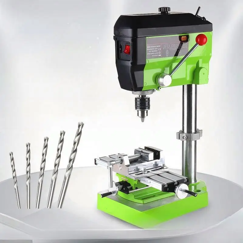
Source-controlled product identity
The Hoting queue record identifies this product as a Bench Drill. The structured fields provide the following source-backed values: 220V voltage, 50-60Hz frequency, 710W power, 0-2800R/MIN no-load speed, 60mm stroke length, 110mm working radius and 1.5-13mm clamping capacity. The application field lists metal, wood boards and plastic materials, while the feature field describes a gear-drive design, a power-off switch and multipurpose use.
The title also says “industrial laser,” “4 inch cross bench pliers,” “drill press stand” and “mini bench drilling machine.” These are listing claims, not replacements for the structured specifications. Product ID 1601276861888 should appear on the quotation, nameplate, datasheet, inspection report and packing list. The source does not provide chuck type, spindle taper, spindle runout, table dimensions, throat depth beyond the working-radius field, column size, overall dimensions, weight, drilling capacity by material, laser specification, vise travel, duty cycle, certification, MOQ, warranty or lead time. Those values remain RFQ and acceptance-test items.
Verified specifications and listing claims
| Source field | Recorded value | Buyer action |
|---|---|---|
| Product Name | Bench Drill | Confirm exact model, nameplate, spindle system, included chuck, table and base configuration. |
| Voltage | 220V | Confirm single-phase or other phase, voltage tolerance, plug, earthing, current and destination configuration. |
| Frequency | 50-60Hz | Confirm whether the same unit supports both frequencies and whether speed or power changes. |
| Power | 710W | Define input versus motor output power, rated current, start-up current and protective-device requirement. |
| No-load Speed | 0-2800R/MIN | Confirm whether this is variable electronic speed, a range of settings or a listing format; obtain loaded-speed data. |
| Stroke Length | 60mm | Confirm spindle or quill travel measurement, stop adjustment, scale and repeatability. |
| Working Radius | 110mm | Confirm the measurement reference, spindle-to-column distance and usable throat depth. |
| Clamping Capacity | 1.5-13mm | Confirm chuck type, minimum and maximum tool shank, runout and compatibility with the buyer’s bits. |
| Application | Metal, wood boards and plastic materials | Request a material-specific drilling chart, speed, bit, feed and lubricant recommendations. |
| Feature claims | Gear drive, power-off switch, multipurpose automatic/precision wording | Verify gear train, controls, safety function and whether “automatic” describes feed or only marketing copy. |
| Title claims | Laser, 4 inch cross bench pliers, mini/industrial | Confirm laser presence/specification, vise size and travel, machine class and actual included accessories. |
Electrical configuration for a 220V, 50-60Hz machine
The structured voltage is 220V and the frequency is 50-60Hz. Request the nameplate, wiring diagram and destination plug before ordering. Confirm the phase, rated current, maximum current, earth connection, cable length, fuse or breaker recommendation and allowable voltage tolerance.
Ask whether 50Hz and 60Hz operation use the same motor and gear arrangement. If the motor speed, torque or thermal behavior differs by frequency, the supplier should state the permitted operating range and the relevant test condition. Do not assume that a frequency label alone guarantees identical performance.
Clarify whether 710W means input power or motor output. Request no-load current, loaded current, start-up current and power factor where relevant. Test the unit at the buyer’s actual supply with the intended bit and material. Record current, speed stability, temperature rise and switch behavior.
The power-off switch is a structured feature claim. Confirm its location, latching behavior, restart prevention after a power interruption and compatibility with an emergency stop arrangement. During inspection, disconnect and restore power to verify that the spindle does not restart unexpectedly.
Speed range and drilling process
The source records a no-load speed of 0-2800R/MIN. It does not state the number of speed settings, whether the range is electronic or mechanical, or the loaded speed at different materials. Request the speed-control method, display or scale, adjustment procedure and minimum stable speed.
Build a material-specific drilling chart for the buyer’s work. At minimum, define material, hole diameter, bit type, speed setting, feed method, lubricant or coolant, pecking interval and acceptance condition. Do not use 2800 rpm as a universal drilling speed for every material or bit.
Test speed stability under load. Record the selected setting, measured spindle speed, current, vibration, noise, heat and chip form. Repeat at a small and large hole size within the approved working range. If the spindle slows significantly, request the supplier’s rated-load limit.
Confirm whether the 0 value in the range is a control-display endpoint or simply a way to describe variable speed. A safe purchase specification should state the minimum usable drilling speed, not only the display range.
60mm stroke and depth control
The structured stroke length is 60mm. Ask whether this is quill travel, spindle travel or another measured movement. Request the stroke drawing, scale resolution, depth stop range and repeatability.
Measure the actual travel from the spindle nose or chuck reference to the lowest usable position. Confirm how the stop is locked and whether it remains stable after repeated cycles. Test drilling to a defined depth in a fixture and record the variation across multiple holes.
Define the relationship between 60mm stroke and the tool length, workpiece height, table position and desired hole depth. A 60mm travel value does not by itself confirm that a long bit can reach the workpiece or that a deep hole can be completed without chuck interference.
Ask for a depth-stop instruction and a method to prevent over-travel. The buyer should inspect the return spring, quill guide, handle, stop collar and end-of-travel behavior before approval.
110mm working radius and work envelope
The source records a 110mm working radius but does not define the measurement reference. Request a drawing showing spindle centerline to column, spindle centerline to base edge, usable throat and table area.
Confirm whether the 110mm value is a nominal radial dimension or a usable drilling distance after considering the chuck, guard, vise and workpiece. Test a workpiece near the column and near the outer limit to identify interference and available clamping space.
Ask for table height adjustment, table rotation or tilt, column diameter, base dimensions and mounting-hole pattern. These fields are important when the machine will be integrated into a bench or used with a cross vise.
Keep the working radius separate from hole diameter and drilling capacity. A 110mm radius describes a positioning envelope; it does not establish the maximum diameter or thickness of material that can be drilled.
1.5-13mm clamping capacity and chuck verification
The structured clamping capacity is 1.5-13mm. Request the chuck type, mounting interface, key or keyless operation, minimum and maximum shank, jaw condition, runout and included chuck key or accessories.
Measure runout at the chuck and at a calibrated test bar. Record the gauge method, measurement distance, speed setting and whether the reading changes across the clamping range. A chuck that accepts a 13mm shank may still require a separate holder for specialty tools.
Confirm whether the capacity applies to drill-bit shanks only or also to cutters, sanding drums and other accessories. Ask for the permitted tool geometry, maximum length and balance requirements.
Test a bit near 1.5mm and another near 13mm only if the supplier confirms those tools are appropriate for the machine. Inspect gripping, slip, concentricity and bit release. Do not infer precision from the chuck range alone.
Gear-drive design and mechanical inspection
The feature field describes a gear-drive design without a belt. Request an exploded drawing or service diagram showing gears, shafts, bearings, lubrication points, guards and adjustment components.
Confirm the gear material, lubrication type, service interval and allowable noise. Inspect the housing for access to lubrication points and protection against chips. Ask whether gears are permanently lubricated or require scheduled maintenance.
Run the spindle through the no-load range and listen for gear noise, vibration and resonance. Repeat under a defined drilling load. Record housing temperature after the agreed duty cycle and inspect for oil leakage or abnormal movement.
Ask for replacement gear, bearing, switch, motor and spindle-part numbers. A gear-drive claim is useful only when the supplier can support it with a maintenance procedure and parts availability.
Material-specific procurement checks
The application field lists metal, wood boards and plastic materials, plus the feature description mentions aluminum, composite panels, resin panels, thin metal, circuit boards and precision machining of hard materials. These descriptions broaden the intended use, but they do not establish a tested drilling chart for each material.
Request separate recommended tools and settings for mild steel, stainless steel, aluminum, wood and plastic. Confirm bit material, point angle, speed, feed, lubricant, chip evacuation and maximum hole size for each material.
For wood and plastic, test heat, melting, tear-out, splintering and clamping stability. For metal, inspect burrs, hole roundness, surface finish, work hardening and chip control. For composites or circuit boards, clarify dust control and the permitted tooling.
The phrase “precision machining of hard materials” is a listing statement unless supported by a documented material, hardness, tool, hole size, tolerance and test result. Ask for a sample report before making a precision claim in the purchase order.
Cross vise, laser and accessory verification
The title mentions a 4 inch cross bench pliers, which may refer to a cross-slide vise. The structured record does not include vise jaw width, opening, travel, height, accuracy or whether the vise is included. Request a complete accessory list with part numbers.
Measure the actual vise jaw width and opening if supplied. Confirm X/Y travel, lead-screw backlash, base mounting, clamping method and table compatibility. Test repeatability by drilling a pattern after moving the vise in both directions.
The title also uses “laser.” Ask whether a laser crosshair or line is actually supplied, where it is mounted, its power or classification, adjustment method, alignment tolerance and replacement procedure. Do not state that a laser improves accuracy until alignment has been checked against the spindle centerline.
Verify all included items: chuck, key, vise, table, guard, depth stop, laser module, wrenches, manual, spare parts and packaging. Accessories shown in images may be optional and should not be treated as included without a written quotation.
Table, base and installation
The source does not provide overall dimensions, table dimensions, base thickness, mounting holes or machine weight. Request a dimensioned installation drawing before selecting a bench or stand.
Confirm table flatness, slot layout, tilt or rotation, height adjustment and locking method. Inspect the column-to-base connection and check for movement while feeding a bit into the workpiece.
Test the machine on the buyer’s intended bench. Record vibration, movement, noise and stability with the workpiece clamped. If anchoring is required, obtain bolt size, hole spacing and minimum support thickness.
Leave clearance for the chuck, guard, vise, depth handle, cable and workpiece. A compact listing does not guarantee that the complete operating envelope fits the buyer’s bench.
Safety, guarding and operator workflow
Request the instruction manual and risk assessment for the exact model. Inspect the chuck, rotating spindle, gear housing, guard, power switch, depth stop and workholding arrangement.
Confirm whether the chuck guard is included, adjustable and interlocked. Check that the power-off switch is easy to reach and that the operator can isolate power before changing bits, clearing chips or adjusting the table.
Define the correct use of eye protection, hearing protection, gloves, dust control and workpiece clamps. Gloves should not be used where they can catch in rotating equipment. Long stock must be supported so it cannot swing or rotate.
Run an emergency stop and restart test. Confirm that the spindle stops within the supplier’s stated behavior and does not restart after power restoration. Record the test result in the inspection report.
Factory acceptance test proposal
- Verify product ID 1601276861888, Bench Drill model, 220V nameplate, 50-60Hz rating and 710W power definition.
- Test plug, phase, earth, cable, switch, power-off behavior, restart prevention and protective-device requirements.
- Measure no-load speed across the documented range and record loaded speed under an agreed drilling condition.
- Measure 60mm stroke, depth-stop range, scale repeatability and end-of-travel behavior.
- Verify the 110mm working-radius reference on the drawing and test clearance with the intended workholding.
- Measure chuck capacity from 1.5mm to 13mm where applicable, runout, gripping and bit release.
- Inspect gear-drive noise, vibration, lubrication, heat rise, housing, bearings and replacement parts.
- Test metal, wood and plastic samples with agreed bits, speeds, feeds, lubricants and hole tolerances.
- Verify cross vise, laser, table, guard and other accessories against the written quotation and part list.
- Review installation drawing, safety manual, compliance documents, packing, warranty, MOQ and lead time.
RFQ checklist
- Product ID 1601276861888, exact model, nameplate photograph and current datasheet.
- 220V configuration: phase, tolerance, current, plug, cable, earth, fuse and breaker requirement.
- 50-60Hz operation: motor behavior, permitted frequency range, speed and thermal test conditions.
- 710W definition: input or output power, no-load current, loaded current, start-up current and duty cycle.
- 0-2800R/MIN range: control method, speed settings, loaded speed, accuracy and minimum usable speed.
- 60mm stroke: measurement reference, quill travel, depth stop, scale, lock and repeatability.
- 110mm working radius: drawing reference, throat depth, spindle-to-column distance and usable envelope.
- 1.5-13mm clamping capacity: chuck type, interface, runout, key, jaw range and tool compatibility.
- Gear-drive layout, materials, lubrication, noise, service interval, gears, bearings and spare parts.
- Material-specific drilling data for metal, wood, plastic, aluminum, composites and circuit boards.
- Cross vise details: jaw size, opening, X/Y travel, backlash, mounting and whether included.
- Laser details: presence, module specification, alignment, safety classification and replacement.
- Table, base, column, guard, overall dimensions, weight, mounting holes and installation clearance.
- MOQ, sample inspection, lead time, warranty, manuals, compliance evidence and after-sales service.
Buyer decision framework
This listing is a starting point for sourcing a compact electric bench drill. The source-backed scope includes Bench Drill identity, 220V, 50-60Hz, 710W, 0-2800R/MIN no-load speed, 60mm stroke, 110mm working radius, 1.5-13mm clamping capacity and the stated material applications. The title’s laser, 4-inch cross-vise and industrial/mini wording require model-specific confirmation. Approve the machine only after the supplier demonstrates electrical behavior, speed under load, stroke and throat references, chuck runout, material-specific drilling results, safety functions and the exact accessory package.
Frequently asked questions
Is 2800 rpm the drilling speed for every material?
No. 2800R/MIN is recorded as a no-load speed value. Request loaded-speed data and material-specific recommendations for each bit and workpiece.
Does 1.5-13mm mean the machine includes a 13mm chuck?
It is the recorded clamping-capacity field, but the chuck type and included accessories are not separately specified. Confirm the chuck model, runout, key and actual included item.
Is the machine suitable for metal, wood and plastic?
The application field lists those materials. Confirm the drilling chart, bits, speed, feed, lubricant, hole size and acceptance tolerance for the buyer’s actual material.
Is a laser crosshair included?
“Laser” appears in the title, but the structured record does not confirm the module. Require a written accessory list and verify alignment if supplied.
What does the 60mm stroke measure?
The source records 60mm but does not define the reference. Ask whether it is quill or spindle travel and verify it with a drawing and depth-stop test.
Source and contact
This guide is based on the Hoting queue record for product ID 1601276861888. Before purchase, request the current quotation, nameplate, electrical datasheet, speed and drilling chart, chuck and vise details, laser confirmation, installation drawing, safety manual, packing list, spare-parts offer, warranty and final machine photographs. For sourcing questions, contact the TEBAK sales team through the site’s current inquiry channel.
Key specifications
- Product Name
- Bench Drill
- Voltage
- 220V
- No-load Speed
- 0-2800R/MIN
- Frequency
- 50-60Hz
- Power
- 710W
- Stroke Length
- 60mm
- Working Radius
- 110mm
- Clamping Capacity
- 1.5-13mm
- Application
- Can be widely used metal, wood boards, plastic materials, etc.
- Feature
- Gear drive, power-off switch and multipurpose bench drilling claims; verify exact configuration.