
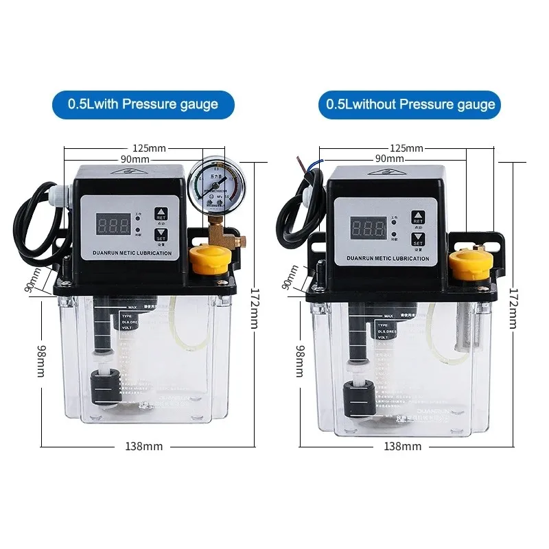
Four parameter rows, and every one of them is a range
This is the whole parameter block, transcribed exactly as published:
| Label | Value |
|---|---|
| Product Name | Automatic Lubricating Oil Pump |
| Voltage | 110V,220V |
| Tank capacity | 0.5-2L |
| Pressure gauge | With/Without |
Four rows, and not one of them is a number you can specify against. “0.5-2L” spans four times the smallest volume. “110V,220V” is two different products with two different plugs. “With/Without” is a binary option, not a property. And the description above the block says only Please contact customer service for the specifications you want.
An oil pump is bought on two figures: how much oil it moves per cycle, and at what pressure. Neither appears anywhere in the parameter block. Both are printed on the nameplate, which is only legible inside the photographs.
The nameplate, read from the photographs
Each tank size has its own image with a dimensioned nameplate. Transcribing all of them gives the real specification set:
| Tank | Type code | Pressure | Voltage | Delivery | Display |
|---|---|---|---|---|---|
| 0.5 L | DBR-50/0.5C | 0.1–1.6 MPa | 220 V | 50 ml/min | single window |
| 1 L | DCR-50/1C | 0.8–1.0 MPa | 220 V | 50 ml/min | two windows |
| 2 L | DBR-50/2C | 0.1–1.6 MPa | 220 V | 50 ml/min | two windows |
The nameplate also carries the oil recommendation: 15# to 68# lubricating oil, which is ISO VG 15 to ISO VG 68 — a viscosity span of roughly four and a half times between the thin and thick ends. That span is not a recommendation, it is a decision left to the buyer, and it depends on ambient temperature and on what the machine's own manual asks for.
So the parameter block gives ranges and the nameplate gives numbers. The nameplate is in a photograph. A buyer who reads only the text knows that a pump exists.
One delivery rate for three tanks
All three models move 50 ml per minute. The tank size does not change the rate, which means the pump element is the same across the family and only the reservoir and the housing differ.
| Tank | Volume | Continuous run-out at 50 ml/min |
|---|---|---|
| 0.5 L (DBR-50/0.5C) | 500 ml | 10.0 min |
| 1 L (DCR-50/1C) | 1,000 ml | 20.0 min |
| 2 L (DBR-50/2C) | 2,000 ml | 40.0 min |
Ten minutes of continuous delivery from the smallest tank is the number that makes the timer meaningful. This pump is not meant to run continuously; it runs for a few seconds and then waits. The waiting is what the second display field controls.
What a cycle actually delivers
The panel sets a run time in seconds and an interval in minutes. Delivery per cycle is the rate multiplied by the run time, so the volume is set by the timer rather than by an orifice:
| Run time | Volume per cycle | 0.5 L cycles | 1 L cycles | 2 L cycles |
|---|---|---|---|---|
| 1 s | 0.83 ml | 600 | 1,200 | 2,400 |
| 5 s | 4.17 ml | 120 | 240 | 480 |
| 10 s | 8.33 ml | 60 | 120 | 240 |
| 15 s | 12.50 ml | 40 | 80 | 160 |
| 30 s | 25.00 ml | 20 | 40 | 80 |
| 60 s | 50.00 ml | 10 | 20 | 40 |
| 120 s | 100.00 ml | 5 | 10 | 20 |
| 300 s | 250.00 ml | 2 | 4 | 8 |
| 600 s | 500.00 ml | 1 | 2 | 4 |
| 999 s | 832.50 ml | 0.6 | 1.2 | 2.4 |
The run range is 1 to 999 seconds, a span of nearly a thousand to one, so the volume per cycle spans the same thousand to one: 0.83 ml at one end and 832.5 ml at the other. Nothing in the listing tells a buyer where in that range their machine should sit.
The maximum run time cannot complete one cycle on the smallest tank
The run time goes to 999 seconds. At 50 ml/min that is 832.5 ml. The smallest tank holds 500 ml.
| Tank | Volume | One 999 s cycle needs | Cycles per fill | Verdict |
|---|---|---|---|---|
| 0.5 L | 500 ml | 832.5 ml | 0.60 | runs dry before the cycle ends |
| 1 L | 1,000 ml | 832.5 ml | 1.20 | one cycle, then a dry start |
| 2 L | 2,000 ml | 832.5 ml | 2.40 | two cycles, then a dry start |
This is not a flaw in the pump; it is a limit that the listing does not state. The run time field accepts a value the reservoir cannot support, and there is no interlock described that would stop the pump when the float drops. Setting the timer at the top of its range on a 0.5 L unit means the pump will run until it is empty and then keep running, which is how a pump element gets destroyed.
The low-level float is visible in the gallery — a cylindrical float on a stem near the bottom of the tank, labelled as a bottom oil level alarm float. Whether that float stops the pump or only signals is not stated. Ask, because the difference is a warning light versus a burned-out motor.
How long a fill lasts, and why tank size is decided by the timer
Take a modest setting of 10 seconds per cycle, which delivers 8.33 ml. The number of cycles per fill is then fixed, and the calendar life of one fill is cycles multiplied by the interval:
| Tank | Cycles per fill | I = 30 min | I = 60 min | I = 120 min | I = 240 min | I = 480 min |
|---|---|---|---|---|---|---|
| 0.5 L | 60 | 1.2 d | 2.5 d | 5.0 d | 10.0 d | 20.0 d |
| 1 L | 120 | 2.5 d | 5.0 d | 10.0 d | 20.0 d | 40.0 d |
| 2 L | 240 | 5.0 d | 10.0 d | 20.0 d | 40.0 d | 80.0 d |
Read the middle column. At a ten-second run every hour, the 0.5 L tank needs refilling every two and a half days. On a machine that runs two shifts, that is a refill roughly every five working days. The 2 L tank under the same setting lasts ten days of calendar time, which is about two working weeks.
So the tank size is not chosen from the machine's size. It is chosen from the timer setting and from how often somebody is willing to walk over with a jug. A shop that sets a long interval can use the 0.5 L unit and refill monthly; a shop that sets a short interval and buys the 0.5 L unit will be refilling twice a week and will eventually stop doing it.
There is a second constraint that the table does not show. Oil in a reservoir is exposed to air and to whatever the machine throws at it. Leaving the same oil in a 2 L tank for eighty days is not obviously better than refilling a 0.5 L tank every twenty days, because the oil at the bottom of the big tank has been sitting there for nearly three months.
Four pressure figures for one product family
Pressure is the number that decides whether this pump can drive the distribution hardware on the machine. Four sources in this catalogue and its images give four answers:
| Source | Pressure | In bar | Span |
|---|---|---|---|
| DBR-50/0.5C nameplate | 0.1–1.6 MPa | 1–16 | 16.0× |
| DCR-50/1C nameplate | 0.8–1.0 MPa | 8–10 | 1.2× |
| DBR-50/2C nameplate | 0.1–1.6 MPa | 1–16 | 16.0× |
| Third image, DCR-5… plate | 0.4–0.7 MPa | 4–7 | 1.7× |
Two of these are wide statements and two are narrow ones. A range of 1 to 16 bar says almost nothing: it is the span from a barely-pressurised line to a modest one. A range of 8 to 10 bar says something useful, because it is a working band. The 0.4 to 0.7 MPa plate is narrower still.
Which is correct? The narrow figures are the more plausible ones for a pump of this size, because a range that spans sixteen times cannot be a controlled working pressure; it is a maximum rating printed as if it were an operating range. But this is inference from the numbers, not a statement from the seller, and the listing does not resolve it. Treat the pressure as unknown until it is confirmed in writing.
16 bar against what a progressive system needs
This matters because the machine it is sold for — a CNC lathe — may use either of two lubrication architectures, and they need very different pressures.
| Architecture | Typical pressure | Against this pump's 16 bar ceiling |
|---|---|---|
| Progressive (series) system, meter-in divider valves | 150–250 bar running; pumps rated to 550 bar | 9.4× to 15.6× too low |
| Progressive system, lower-rated example | 69 bar | 4.3× too low |
| Direct or low-pressure line to resistance metering fittings | single-digit bar | within range |
Those progressive figures come from published system documentation, not from this listing: SKF states pumps supplying metering devices at up to 550 bar, one manufacturer's progressive line is rated at 69 bar, and a system guide quotes 15–25 MPa during operation.
The conclusion is narrow and useful: this pump cannot be the supply for a progressive divider-valve system. It is off by a factor of four at the most generous comparison and by fifteen at the typical one. It belongs on the low-pressure side — a line feeding resistance or throttle metering fittings, which is the common arrangement on a lathe's way and screw lubrication.
If the machine already has a progressive manifold with a row of pistons and indicator pins, this pump is the wrong part and no amount of timer adjustment will fix it. If the machine has a manifold of small adjustable metering fittings fed from a single line, this pump is the right kind of part.
The gauge has no headroom on two of the three models
The gauge fitted is a 1.6 MPa unit. A pressure gauge is normally selected so that the working pressure falls in the middle of the dial, leaving room above for surges and below for reading.
| Model | Stated upper pressure | Position on a 1.6 MPa dial | Headroom |
|---|---|---|---|
| DBR-50/0.5C | 1.6 MPa | 100% of full scale | 1.00× |
| DBR-50/2C | 1.6 MPa | 100% of full scale | 1.00× |
| DCR-50/1C | 1.0 MPa | 62% of full scale | 1.60× |
| Third image plate | 0.7 MPa | 44% of full scale | 2.29× |
On the 0.5 L and 2 L plates the stated maximum is exactly the gauge's full scale. If the pump can genuinely reach 1.6 MPa, the needle sits on the end stop and a small overpressure has nowhere to register. A gauge should be rated above the pressure it is expected to see, and here it is rated exactly at it.
The other reading is that the 1.6 MPa figure is a gauge rating copied into the pressure field rather than a pump capability, which would explain the exact match and would also explain why the same slot reads 0.8–1.0 MPa on the 1 L model. Either way, the buyer cannot tell from the page which it is, and one of the two readings makes the gauge undersized.
Two model prefixes and two different display panels
The family uses two prefixes and they do not follow the tank size:
| Tank | Prefix | Display | Buttons | Shows run and interval together? |
|---|---|---|---|---|
| 0.5 L | DBR | one window | RET, SET, down | no, one value at a time |
| 1 L | DCR | two windows | Set, up, down, manual | yes |
| 2 L | DBR | two windows | Set, up, down, manual | yes |
So DCR is not a different product class; it is the 1 L model, and the 2 L model with the same two-window panel reverts to DBR. Whatever DBR and DCR encode, it is not the display type and it is not the tank size.
Two practical consequences. First, the 0.5 L panel has one display and one fewer button than the other two, so setting it is a different sequence and the manual for one will not match the other. Second, the 0.5 L panel has no manual-run button, while the 1 L and 2 L panels do. If commissioning involves purging the lines by hand, that button is the difference between a two-minute job and a menu walk.
What the gallery does show, and it is worth having
Several features appear only in the photographs, and they are real:
| Feature | Where it is visible | Why it matters |
|---|---|---|
| Low-level float | a float on a stem near the tank bottom | the only defence against running dry |
| Suction filter | a gauze element on the pick-up tube | keeps chips out of the pump element; needs cleaning |
| Hinged filler cap | a yellow flip cap on the top plate | refilling without removing the lid |
| Fastening flange with slotted holes | two ears with slots at the ends | mounting on a machine panel without a drilled template |
| Level window with MAX and MIN marks | moulded into the tank wall | a visual check without the float circuit |
| Pressure gauge on the outlet side | brass standpipe beside the cap | the only way to know the line is actually pressurising |
None of these is in the parameter block, and each of them is something a buyer would want to know before ordering. The slotted mounting flange is the one that saves the most work, because the hole spacing varies by tank size — 91 to 125 mm on the 0.5 L, 97 to 125 mm on the 1 L, and a single 145 mm figure on the 2 L — and a slot accommodates that variation where a drilled hole does not.
Two envelopes published for the same 1 L model
One image gives the 1 L unit as 142 by 190 mm; a different image in the same gallery gives the same model as 142 by 200 mm.
| Tank | Width | Height | Tank body height | Mounting hole spacing |
|---|---|---|---|---|
| 0.5 L | 138 mm | 172 mm | 98 mm | 91–125 mm |
| 1 L | 142 mm | 190 mm | 110 mm | 97–125 mm |
| 1 L, other image | 142 mm | 200 mm | 110 mm | 97–125 mm |
| 2 L | 192 mm | 225 mm | 135 mm | 145 mm |
The discrepancy is 10 mm, or 5.3% of the smaller figure. That sounds trivial until the pump has to go under a machine cover, into a guard, or behind a panel on a lathe where the available height was measured from the smaller drawing. Ten millimetres is the difference between fitting and not fitting.
The interesting part is the scaling. Going from 0.5 L to 2 L quadruples the oil but grows the width by only 1.39 times and the height by 1.31 times. The tank gets proportionally deeper rather than much bigger in footprint, which is good news for mounting and bad news for reaching the bottom of the tank when cleaning it out.
The interval field is labelled in minutes and annotated in points
The screen prints INTERVAL (min). An English annotation drawn over a photograph of the same panel reads Interval (1~999points). Points is not a unit of time; the field is minutes, and the annotation is a mistranslation of the Chinese for minutes.
| Field | Range | In seconds |
|---|---|---|
| Run time | 1–999 s | 1–999 s |
| Interval | 1–999 min | 60–59,940 s |
The two fields overlap awkwardly: the shortest interval is 60 seconds, so a cycle can never repeat faster than once a minute, while the run time can be as long as 999 seconds. A run of 999 seconds with an interval of one minute is a pump that restarts before it has finished, which the controller presumably handles by restarting the count after the run ends rather than from the start of the run. Which of those two behaviours it uses decides the real duty cycle, and no documentation describes it.
999 minutes is 16.6 hours. That upper bound is why the 2 L tank can be made to last eighty days, and it is also why a setting left at the factory default could be delivering oil once a day to a machine that needs it once an hour.
Two listings, one product
The catalogue carries this pump twice. The other listing uses the code HPS02 in its title, describes the same pump as an electromagnetic unit with a dual digital display, and carries a parameter block that is row-for-row identical to this one — Product Name, Voltage, Tank capacity, Pressure gauge, same four values. The two listings share two of their eight images.
| This listing | The other listing | |
|---|---|---|
| Title code | none, just 220V 1L 2L | HPS02 |
| Parameter block | four rows, all ranges | identical four rows |
| Images | 8, including the dimensioned nameplates | 8, two shared |
| Extra wording | none | dual digital display, electromagnetic |
So HPS02 and the DBR/DCR codes are three naming systems for one family, and the code that appears on the nameplate is the one to quote in an order. A purchase order written against “HPS02” and a nameplate reading DBR-50/2C is a discrepancy waiting to happen at goods-in inspection.
What to put in the request for quotation
| # | Question | Why it decides the purchase |
|---|---|---|
| 1 | Which nameplate code ships: DBR-50/0.5C, DCR-50/1C or DBR-50/2C | the three differ in volume and in panel, and the codes are printed on the product |
| 2 | The actual delivery pressure, as a working band and not a span | plates say 0.1–1.6, 0.8–1.0 and 0.4–0.7 MPa; the first is a 16× span, not a band |
| 3 | Whether 50 ml/min is at free flow or against the rated pressure | a pump delivering 50 ml/min at zero back pressure may deliver much less at 10 bar |
| 4 | Whether the low-level float stops the pump or only signals | a 999 s cycle on a 0.5 L tank empties it; only one of the two behaviours saves the pump |
| 5 | Motor power, current and whether 110 V is a different motor or a transformer | none of these appears anywhere; the block just says 110V,220V |
| 6 | Number of outlets and the outlet thread | not stated; decides how the line connects to the manifold |
| 7 | Which oil viscosity for the ambient temperature on site | the plate allows ISO VG 15 to 68, a 4.5× span, with no guidance |
| 8 | The true overall height of the 1 L unit | two drawings give 190 mm and 200 mm, a 10 mm difference that decides whether it fits under a cover |
| 9 | Whether the timer restarts from the end of the run or from the start | decides the real duty cycle when run time approaches the interval |
| 10 | Ingress protection and operating temperature range | neither is stated, and a lathe throws coolant |
| 11 | Weight, and whether the mounting flange is included | weight absent from the page; the slotted flange is visible in a photo only |
| 12 | A spare filter element and the float part number | both are consumables and neither is listed |
Question 1 and question 3 are the ones that decide whether the pump works on your machine. Question 4 decides whether it survives its first month.
What this pump is good for, and what it is not
| Good fit | Poor fit |
|---|---|
| Low-pressure line feeding resistance or throttle metering fittings on ways and screws | A progressive system with divider valves and indicator pins, which needs 4–15 times this pressure |
| Machines where a refill every one to three weeks is acceptable | Unattended machines where a 0.5 L tank on a short interval would run dry between shifts |
| Retrofit onto a lathe whose original pump is a similar low-pressure unit | Any machine where the existing manifold is a piston divider block |
| Shops that will confirm the nameplate code, the pressure band and the float behaviour in writing | Buyers who read four parameter rows and expect to have specified a pump |
The honest summary: the pump is a straightforward low-pressure oil unit with a timer, a float, a filter and a level window, and those parts are visible and plausible. What the page does not give is the two numbers that define it — a working pressure band and a delivery rate under load — and it offers four mutually inconsistent pressure figures instead. The tank size question, which looks like the main choice, turns out to be the least important one, because the timer decides consumption and the tank only decides how often somebody refills.
Key specifications
- Product Name
- Automatic Lubricating Oil Pump
- Voltage
- 110V,220V
- Tank capacity
- 0.5-2L
- Pressure gauge
- With/Without
Frequently asked questions
- How much oil does this pump deliver?
- Fifty millilitres per minute on all three tank sizes, according to the nameplate printed inside the images. That is the free-flow figure the plate states; whether it holds against a pressurised line is not published. Because the rate is the same across the family, the tank size does not change the delivery, only how long a fill lasts before somebody refills it.
- Which tank size should I buy, 0.5 L, 1 L or 2 L?
- It depends on the timer setting rather than on the machine size. At ten seconds run every sixty minutes, a 0.5 L tank lasts about two and a half days, a 1 L tank five days and a 2 L tank ten days. If the interval is set longer, the small tank lasts proportionally longer: a 0.5 L unit at ten seconds every eight hours lasts about twenty days. Choose the tank by how often you are willing to refill, not by the footprint of the machine.
- What pressure does it produce?
- The catalogue gives four different answers. The 0.5 L and 2 L nameplates say 0.1 to 1.6 MPa, the 1 L nameplate says 0.8 to 1.0 MPa, and a plate in a third image says 0.4 to 0.7 MPa. The first is a span of sixteen times, which is a rating rather than a working band. Ask for the working band in writing; the narrow figures are the plausible ones for a pump of this size.
- Can it drive a progressive lubrication system?
- No, not on the published figures. Progressive systems with divider valves run at roughly 150 to 250 bar, and pumps for them are rated to several hundred bar, with one lower-rated line at 69 bar. This pump's highest stated ceiling is 1.6 MPa, which is 16 bar: four to fifteen times too low. It belongs on a low-pressure line feeding resistance or throttle metering fittings, which is the usual arrangement for lathe ways and screws.
- What happens if I set the run time to maximum?
- The run field accepts up to 999 seconds. At 50 ml/min that is 832.5 ml in one cycle, which is more than the 0.5 L tank holds. The 1 L tank manages one such cycle and the 2 L tank two, and in both cases the next cycle starts dry. There is a low-level float in the tank, but the listing does not say whether it stops the pump or merely signals, so on a 0.5 L unit a maximum setting will empty the tank mid-cycle.
- Why is the interval labelled points in one image?
- Because it is a mistranslation. The screen itself prints Interval (min), and the field runs from 1 to 999 minutes, which is 16.6 hours at the top of the range. The word points comes from translating the Chinese for minutes incorrectly. The run field is separate and runs from 1 to 999 seconds.
- Is the 1 L model a different product from the 0.5 L and 2 L?
- It uses a different prefix, DCR against DBR, and it has a two-window display while the 0.5 L has a single window. But the 2 L model also has a two-window display and goes back to DBR, so the prefix does not encode the display or the volume. The practical differences are the panel button set and the fact that the 0.5 L panel has no manual-run button.