
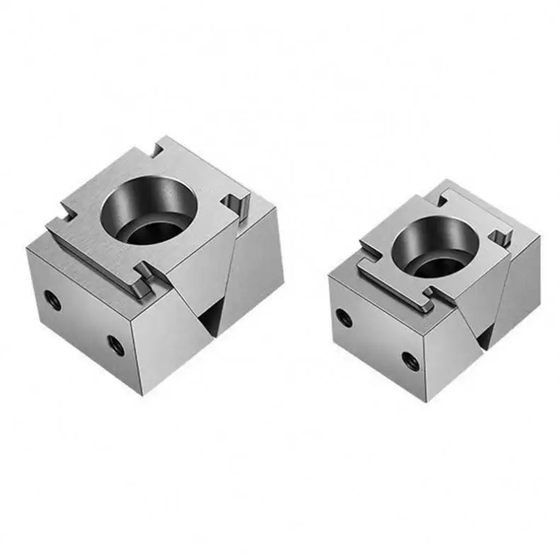
A clamp that closes outward, not inward
Almost every workholding device in a machine shop closes on a part from the outside. A machine vise brings a moving jaw toward a fixed one. A strap clamp pushes down. A three-jaw chuck squeezes radially inward. The element described on this page does the opposite of all of them: it is placed in a bore, a slot or a pocket, and it expands. Two half-bodies are driven apart in parallel and hold the workpiece by pushing outward against it.
That single reversal is the whole reason the part exists, and it changes what a buyer has to specify. You are not shopping for jaw width or throat depth. You are shopping for an expansion range, for the squareness of two faces that move away from each other, and for how far those faces travel per side before the wedge runs out of stroke. None of those three numbers is a headline figure in the catalogue, and one of the two figures the catalogue does give contradicts the other for four of the six sizes. Sorting that out is what this guide is for.
The record is product ID 1601255794756. The catalogue calls it, variously, a precision modular wedge clamping element, a wedge clamp, a MINI OK vise and a precision modular single vise — five names for one mechanism, which is worth knowing before you search for it. Its parameter block has six rows and they read: Customized support OEM; Brand Name TEBAK; Model Number M6 M8 M10 M12 M14 M16; Power Manual; Number of Jaws Other; Material Steel. Of those six, one is a material family rather than a grade, one is a count answered with the word Other, and one tells you the device is hand-driven unless you change it. Everything else you need arrives as artwork.
The size table, transcribed exactly
The dimensional data lives in a single panel headed Model parameters of steel type, laid out as six cards, one per model. The panel gives three dimensions and a range for each card. Read literally, the three dimensions are length, width and height, and the range is printed under the labels extension range (M6, M8, M12, M14) or scope (M10, M16) — two different words for what is almost certainly the same quantity.
| Model | Size, L × W × H (mm) | Stated range (mm) |
|---|---|---|
| M6 | 28.4 × 19.3 × 14.8 | 28.4–31 |
| M8 | 36 × 24.5 × 19.5 | 36–41 |
| M10 | 36 × 29.5 × 19.7 | 35.7–41.8 |
| M12 | 44 × 30 × 24.5 | 44–48 |
| M14 | 48 × 38 × 25 | 48–54 |
| M16 | 57.2 × 45.5 × 29.8 | 57.2–64.2 |
Two things are already visible in that table before any arithmetic. First, M8 and M10 share a length of 36 mm but differ in width by 5 mm and in height by 0.2 mm, so they are not the same body with a different bore — they are separate castings or billets. Second, the tallest model is not proportionally the longest: M16 is 2.01 times the length of M6 but 2.01 times its height as well, while its width grows by 2.36 times. The family scales in width faster than in length, which is what you would expect from a wedge whose load path widens as the bodies grow.
What the panel does not give: mass, mounting hole diameter or spacing, the thread inside the central bore, the material grade behind the word Steel, the surface treatment, or any tolerance on the three dimensions. Each of those is a question for the supplier, and the last section turns them into a checklist.
The arithmetic the table invites, and the disagreement it exposes
The range column only becomes useful when you subtract its lower bound from its upper bound. Do that, halve the result, and you have the travel each clamping face makes if the range is measured across the whole assembly and the two halves move symmetrically — which is what the motion diagram says they do, in parallel and at the same time.
| Model | Range low | Range high | Span | Span ÷ 2, per side | Against the 0.5–2.0 figure |
|---|---|---|---|---|---|
| M6 | 28.4 | 31 | 2.6 | 1.3 | inside 0.5–2.0 |
| M8 | 36 | 41 | 5 | 2.5 | above 2.0 |
| M10 | 35.7 | 41.8 | 6.1 | 3.05 | above 2.0 |
| M12 | 44 | 48 | 4 | 2 | inside 0.5–2.0 |
| M14 | 48 | 54 | 6 | 3 | above 2.0 |
| M16 | 57.2 | 64.2 | 7 | 3.5 | above 2.0 |
Here is the problem. A separate panel in the same catalogue states, in a caption under a photograph of the clamp holding two copper blocks, Fixture single-side open 0.5-2.0. If that caption means what it says — every model opens between 0.5 mm and 2.0 mm on each side — then only M6 (1.3 mm per side) and M12 (2.0 mm per side) comply. M8 sits at 2.5 mm, M10 at 3.05 mm, M14 at 3.0 mm and M16 at 3.5 mm, all of which exceed the stated ceiling by 25 to 53 percent.
Three readings are possible and the catalogue does not tell you which one is intended:
- The caption describes only the smallest body. On this reading 0.5–2.0 is a service range quoted for M6 and simply not restated for the larger models. It is the most charitable interpretation and the easiest to test: ask for the per-side stroke of M8 through M16.
- The range column is not a jaw gap. If 28.4–31 for M6 is the overall length of the assembly from fully closed to fully open, then the per-side travel is the span divided by two and the numbers above are correct — which then makes the 0.5–2.0 caption wrong or model-specific. This reading is supported by the next section.
- The two figures were authored by different people from different drawings. Common in catalogue artwork assembled from a factory's own slide deck; the caption may predate a redesign that increased stroke.
The practical consequence is blunt: if you are buying this clamp to absorb a stack of stock that varies by, say, 3 mm, the answer for M8 and above depends entirely on which reading is true, and guessing in the wrong direction means either a clamp that will not release or one that will not grip. This is the first line of the RFQ, not a footnote.
Why the lower bound equals the block length on five of six models
Look again at the two left-hand numeric columns. For M6 the length is 28.4 and the range starts at 28.4. For M8 it is 36 and 36. M12: 44 and 44. M14: 48 and 48. M16: 57.2 and 57.2. Five of the six models start their range at exactly their own length, to the tenth of a millimetre. M10 is the single exception, with a length of 36 and a range starting at 35.7 — three tenths lower.
Five exact coincidences are not a coincidence. They are a definition. The range column is very probably the overall span of the assembly measured along the axis of expansion, from the closed state (where the two halves are butted and the span equals the body length) to the open state (where they have separated). That is a sensible thing to publish, because it is the dimension that has to fit in your pocket or between your fixtures. It is also not the dimension most machinists assume when they read the word range on a clamp, and confusing the two is how a buyer ends up with a body that is 4 mm too long for the slot it was meant to sit in.
The M10 anomaly is the interesting part. A 0.3 mm shortfall against its own length suggests either a rounding slip in transcription, a shim or spacer inside that body, or a slightly different closed-state geometry for that one size. It is small enough to be harmless in a rough application and large enough to matter if you are using the closed length as a locating dimension. Ask for a drawing with the closed overall length called out per model; with that single dimension you can compute everything else.
Mass you will actually pay freight on
No weight is published for any of the six sizes, which is awkward because these parts ship in multiples and air freight is priced by chargeable weight. You can bracket the answer without a scale. Take the three published dimensions, multiply them into a rectangular envelope, and multiply by the density of steel at 7.85 g/cm³. The result is an upper bound: the real part is a wedge with material removed from the underside, so it will weigh less, but it cannot weigh more.
| Model | Envelope volume (mm³) | Envelope mass at 7.85 g/cm³ (g) | Published mass |
|---|---|---|---|
| M6 | 8112.2 | 63.7 | — |
| M8 | 17199 | 135 | — |
| M10 | 20921.4 | 164.2 | — |
| M12 | 32340 | 253.9 | — |
| M14 | 45600 | 358 | — |
| M16 | 77557.5 | 608.8 | — |
These are arithmetic on the catalogue's own dimensions, not catalogue figures, and the last column is empty because the supplier has not published one. Two uses follow. For freight, sum the envelope masses and treat the total as the ceiling for a shipment of any given quantity — a hundred M16 bodies cannot exceed roughly 61 kg gross before packaging, which is enough to know whether you are in a courier bracket or an air-freight bracket before you ask for a quote. For handling, the M14 and M16 bodies are the point at which a manual clamp stops being something you hold in two fingers while you start the screw.
How the wedge works, in the supplier's own labels
The motion diagram is the most informative panel in the whole listing, and it is worth quoting rather than paraphrasing because the geometry is the product. Three parts are labelled: A is the central wedge driven by the actuating screw through the threaded bore; B and C are the two half-bodies that carry the clamping faces. The diagram's caption reads:
When A presses down, B and C push out parallel at the same time to reach the purpose of clamping the workpiece.
And for the release stroke:
When A is loosened up, B and C moves back to the inner parallel base bottom at the same time to unlock the workpiece. (Note: When A is loosened upwards, due to the built-in stainless steel spring, B and C will not move upwards with A, but will move backward after sticking to the bottom in parallel inward at the same time.)
Read together, those two sentences describe a self-releasing expansion element with a spring return, and they explain why the part can be used in a horizontal setup where gravity will not help. The wedge angle is not published. That is a real gap, because the wedge angle sets the ratio between screw torque and clamping force, and it also sets whether the element is self-locking: a shallow enough wedge holds without the screw backing out under load, a steeper one does not. For manual use the supplier presumably chose a self-locking angle, but presuming is not the same as knowing, and a buyer sizing a clamp for a roughing cut needs the number.
The spring is the reason it releases
Of everything in the motion diagram, the sentence about the built-in stainless steel spring is the one that decides whether the part is pleasant or infuriating to use. Without a return element, releasing an expanded clamp means the operator loosens the screw and then taps or pries the two half-bodies back into the closed position, on every cycle, with a workpiece that may have sprung against them. With the spring, loosening the screw is sufficient: the halves retract on their own while the wedge lifts clear.
Two engineering notes follow from the wording. The spring is stainless, which is the right choice for a part that lives near coolant and swarf, and it is a wear item — springs in a clamped-and-released cycle work harden, and a fatigued return spring shows up as a clamp that grips but does not let go cleanly. Ask whether the spring is available as a spare and whether it can be replaced in the field without pressing the body apart. The second note is subtler: because B and C stay at the bottom of their travel while A lifts, the wedge's flanks slide against the half-bodies through the whole release stroke. That is the wear surface of the assembly, and it is the surface whose finish and hardness matter most — which is exactly where the catalogue gives you a word (Steel) rather than a specification.
Two ways to drive A, and why the choice is not cosmetic
One line in the artwork opens the door to automation: Tip: The upper and lower parts of A can be controlled by screws or cylinders. The parameter block, meanwhile, says Power: Manual. Both are correct at once — the standard article is hand-driven, and the body is designed so that the same wedge can be pushed by a cylinder instead of a screw.
That difference is not a convenience. Driving A with a cylinder converts a hand tool into a fixture element with a known clamping force, a fixed stroke and a repeatable release, and it lets the clamp live inside a cycle instead of at the end of an operator's arm. But it also imposes requirements the manual version does not have: a cylinder with enough stroke to cover the per-side travel you established earlier, a mounting interface that keeps the rod coaxial with the bore, a force calculation that accounts for wedge friction rather than just dividing by the mechanical advantage, and a control arrangement that fails safe if air pressure drops mid-cut. If you intend cylinder actuation, say so at RFQ — the standard body may need a different top fitting, and Customized support: OEM is the row that tells you the supplier expects to be asked.
What the word Steel leaves open
The material row says Steel and stops. No grade, no heat-treatment specification, no case depth, no surface treatment, no hardness scale. The feature panels add three process notes — chamfering, a diamond-angle arc transition at the corners, and a bright thread ground from the primary millstone — but all three describe finish and edge treatment, not metallurgy.
For this particular part the gap is more consequential than it would be on a bracket, because the load path is two sliding wedge flanks under high surface pressure. Three different steels could all honestly be called Steel and would behave completely differently:
- Through-hardened alloy steel at a uniform hardness holds its shape and resists indentation, but two hard surfaces sliding on each other at high pressure are candidates for galling unless the finish and lubrication are controlled.
- Case-carburised steel gives a very hard skin over a tough core — good for impact and for the fatigue load a clamp sees in a milling cycle, but the case depth has to be right or the flank crushes through the hard layer.
- Pre-hardened tool steel machines well and holds tolerance, at the cost of lower surface hardness and faster wear on the sliding faces.
Whichever the supplier uses, the request is the same: grade, heat treatment, hardness with its scale, and — if carburised — case depth. That takes one line in an email and it is the difference between a clamp you can reorder in two years and one you cannot identify.
Reading "hardness about 40" and "accuracy 0.2" before you commit
The feature panel makes two quantitative claims, and both are missing the thing that makes a number usable.
Hardness is about 40 after tempering and strengthening. Forty on which scale? HRC 40 corresponds to roughly 371 HV and is a sensible hardness for a clamp body that must resist indentation without becoming brittle; 40 HRB would be softer than mild steel and 40 HV would be nearly unhardened. The phrase tempering and strengthening points towards a quench-and-temper route on a medium-carbon or alloy grade, which in practice usually lands somewhere near HRC 40 — but the catalogue does not say HRC, and a purchase order should not assume it. Ask for the scale, the target window, and where on the part it is measured. A clamp body is not uniform; the flank and the mounting face will not read the same.
Accuracy reaches 0.2. No unit, no datum, no length over which it applies. If it is 0.2 mm it is a positional claim loose enough to be met by almost any machined body. If it is 0.02 mm it is a parallelism or squareness claim of a completely different class, and the two differ by a factor of ten. Which one it is decides whether the part is suitable for locating a workpiece that will be milled to a ±0.05 mm tolerance, or only for holding a blank while it is roughed.
There is a third number that matters more than either and appears nowhere in the listing: the parallelism of the two clamping faces through their stroke, and the repeatability of re-clamping the same part. On an expanding element these two govern whether the workpiece moves between operations. Ask for them explicitly, and ask how they are verified — a dial indicator on a granite plate with a gauge block stack is enough, and a supplier who cannot describe that check has not measured it.
Five fixtures share this catalogue, and picking the wrong one is easy
One panel in the listing is not about the M6–M16 element at all. It is a family photograph of five related fixtures, labelled in Chinese, and each one solves a different holding problem. Translated, the labels read:
- Double-sided toothed-face clamp — serrated clamping faces. The teeth bite into the workpiece, so it grips rough castings and forgings well and leaves marks doing it. Right for a first operation on unfinished stock, wrong for anything already machined.
- Double-sided OK clamp — plain, smooth faces. This is the general-purpose version and the one whose geometry matches the six-card size table: a plain body, a central bore, two side holes, chamfered edges.
- Seagull clamp — an angled or hooked profile that clamps from the edge, for the case where the top face of the workpiece has to stay clear for the cutter.
- Extended-length double-sided OK clamp — a longer body on the same principle, for deep parts or for reaching past an obstruction.
- Parallel vise — two clamping stations on a common serrated base rail, which is the shape you want when a pallet carries several identical parts and you would rather build one fixture than six.
These are catalogue labels, not a formal series nomenclature, and none of them carries its own size table in the listing. Two practical rules follow. First, confirm in writing which of the five the M6–M16 table describes — everything in this guide assumes the OK type, because that is the body shown in the dimension cards. Second, if your requirement is really one of the other four, the M-numbered table will not size it for you, and asking for dimensions against the wrong drawing is the fastest way to receive a clamp that does not fit.
Mounting, clearance, and the space the clamp needs around it
The photographs show the body clearly enough to describe the interface even though no drawing is published: two through holes on one side face, a central threaded bore through the wedge, chamfered corners and edges all round, and a flat base. What is not published is the diameter of those side holes, their thread if they are threaded, their centre-to-centre spacing, their depth, or the size of the central thread per model.
The central thread deserves its own note. The feature panel calls it a bright thread ground from the primary millstone, which confirms the bore is threaded — the actuating screw runs in it. The model designations M6 through M16 are, on their face, ISO metric thread sizes, and the obvious guess is that M8 means an M8 actuating thread. That guess is worth testing rather than trusting, because the same designations could equally describe a mounting thread or a body size class, and the length of the M6 body (28.4 mm) is much larger than an M6 thread needs. Ask for the bore thread per model; if M8 does mean an M8 screw, then the tightening torque you can apply is bounded by that thread, and the clamping force follows from it.
Clearance planning has three parts. Along the axis of expansion the body needs room for its full stated span plus a millimetre of margin, because the range column is a capacity, not a target. Across the axis of expansion the body needs only its width, but the mounting screws need head clearance and a tool path. Above the wedge, the actuating screw needs its own headroom, and on a cylinder-actuated version that becomes the cylinder body plus its fittings — the dimension that most often turns a neat fixture design into a collision with the spindle nose.
Incoming inspection on the first delivery
A clamp is cheap enough that buyers tend to skip first-article inspection and expensive enough that a bad batch quietly ruins parts for months. The checks below use equipment a normal toolroom already owns, and they take about an hour for a first delivery across all six sizes.
- Length, width and height against the six-card table, with a caliper or micrometer. This catches a body machined to the wrong size class, which happens when a factory substitutes a neighbouring model during a stock-out.
- Closed overall length. The dimension that five of six models set equal to their own length. Measure it closed; if it is not the table's lower bound, the range column is not describing what you think it is, and you have learned that on arrival rather than in production.
- Full travel. Open the clamp to its stop and measure the span. Compare with the upper bound. If the per-side travel comes out near the 0.5–2.0 caption rather than the range column, the catalogue's two figures have been reconciled for you.
- Parallelism of the two clamping faces through the stroke, with a dial indicator on a surface plate. Take readings closed, mid-travel and open. A clamp that is parallel closed and tapers open will tilt the workpiece.
- Hardness at three points per body with a portable tester, comparing against the scale and window the supplier confirmed. Reject a body that reads far below the agreed value on the flank — that is the wear surface.
- Thread with a go/no-go gauge on the central bore, and on the side holes if they are threaded. A bright thread can still be a tight thread.
- Spring return. Loosen from full clamp and confirm both halves retract without a tap. Do it twenty times on one sample; a marginal spring shows up as sluggishness, not failure.
- Burrs and chamfer. Run a finger along the clamping faces and the wedge flanks. A raised burr on a clamping face becomes an indentation in the workpiece on the first cycle.
- Marking and packaging. Model designation on the body or the box, rust preventive present, parts separated so that faces do not rub in transit. Include this because unmarked clamps from two suppliers become indistinguishable in a crib within a month.
What to put in the RFQ
Every row below exists because the listing does not answer it. Send the table as it stands, with your application filled in against the last two rows, and the reply will be specific instead of a copy of the web page.
| Item to confirm | Why it changes the order |
|---|---|
| Material grade and heat treatment | Decides wear life on the wedge flanks and whether the part can be reordered identically in two years |
| Hardness value, scale and measuring location | “About 40” is not orderable; HRC 40 and 40 HRB are different products |
| Accuracy: value, unit, datum and the surface it applies to | 0.2 mm and 0.02 mm differ by a factor of ten and select different applications |
| Definition of the size range, per model | Reconciles the range column against the 0.5–2.0 single-side caption and sets your stock tolerance |
| Per-side stroke, M6 to M16, individually | The single number that decides whether the clamp absorbs your stock variation |
| Central bore thread per model | Sets the actuating screw, the torque you can apply and therefore the clamping force |
| Mounting hole pattern: diameter, thread, pitch, depth | Without it the fixture plate cannot be designed or drilled in advance |
| Dimensional drawing with tolerances | Converts every number in the table from nominal to inspectable |
| Mass per model | Freight brackets and handling; the envelope figures in this guide are only upper bounds |
| Surface treatment and rust preventive | Decides whether the clamp survives a humid shop or a sea container |
| Spare springs and replacement wedge availability | Turns a consumable into a repairable fixture element |
| OEM branding and marking | Customized support is listed as OEM; confirm what is marked and where |
| MOQ, price breaks and lead time per size | Quoted per configuration rather than published; ask per model, not for the family |
| Your stock tolerance and the cut you intend to take | Lets the supplier size the model instead of you guessing from a table |
| Actuation: manual screw or cylinder | Manual is standard; cylinder changes the top fitting and the force calculation |
When this element earns its price, and when a vise is the better buy
An expanding wedge clamp is a specialist answer, and specialists are worth their cost only when the question is the one they answer. It earns its place in four situations: clamping inside a bore or a pocket where no jaw can reach; holding a part that must be located from its internal feature rather than its outside; holding two faces outward so the part stays centred instead of being pushed against one fixed jaw; and arraying several clamps on a plate to hold a thin or awkward part at multiple points without a custom soft-jaw set.
It is the wrong purchase in three others. If the stock varies more than the per-side travel you establish, the clamp cannot follow it and you will be shimming. If cycle time is set by an operator turning a screw, the manual version will be the slowest station on the machine, and the cylinder version only pays when the volume justifies the fixture work. And if the part is a simple block in an open setup, a conventional vise with the right jaws is cheaper, faster to set and easier to inspect.
The sizing rule that follows is short. Choose the smallest model whose per-side travel covers your stock variation with margin, then check that its closed length and its width fit the space you have, then confirm the actuating thread and the mounting pattern before anyone draws a plate. Buying the largest model for safety is the common error: it costs more, weighs more, needs more clearance, and does not grip better on a part that a smaller body already fits.
What we will and will not quote from this page
This guide publishes the numbers the catalogue itself prints, transcribes them without adjustment, and flags the two that cannot both be true rather than picking the more convenient one. Every derived figure — the span, the per-side travel, the envelope mass — is arithmetic on those printed numbers, labelled as such and reproduced so you can check it with a calculator.
What we will not do is fill the gaps with plausible-sounding values. The material grade, the hardness scale, the unit behind the accuracy figure, the thread in the bore, the mounting pattern, the mass, the MOQ, the price breaks and the lead time are all genuinely unpublished in the source data. We quote them per configuration, per size, once they are confirmed against the drawing — which is also the only way a quotation on a part like this is worth anything to you.
The parts come through TEBAK, supplied from Hebei, China, with OEM marking available on request. If you send the model or models you are considering together with your stock tolerance, the cut you intend and the space the clamp has to fit, the reply will address those three things specifically.
Key specifications
- Customized support
- OEM
- Brand Name
- TEBAK
- Model Number
- M6 M8 M10 M12 M14 M16
- Power
- Manual
- Number of Jaws
- Other
- Material
- Steel
Frequently asked questions
- What does the M6 to M16 designation mean?
- It is the model designation printed in the catalogue's size table, where M6 is the smallest body at 28.4 x 19.3 x 14.8 mm and M16 the largest at 57.2 x 45.5 x 29.8 mm. The letters and numbers follow ISO metric thread sizes, but the listing does not state whether the number refers to the actuating thread in the central bore, a mounting thread, or a body size class. Confirm the bore thread per model before ordering.
- How far does the clamp open on each side?
- Two figures are published and they disagree. The size table gives a range per model; halving each range gives 1.3 mm per side for M6, 2.5 mm for M8, 3.05 mm for M10, 2.0 mm for M12, 3.0 mm for M14 and 3.5 mm for M16. A separate caption in the same catalogue states single-side open 0.5-2.0, which only M6 and M12 satisfy. Ask the supplier to reconcile the two, and specify against the answer rather than against either figure.
- What holds the two jaws apart when the screw is released?
- A built-in stainless steel spring. The catalogue's motion diagram states that when the wedge is loosened, the two half-bodies move back to the inner parallel base together rather than travelling up with the wedge. That is what makes the clamp release without an operator prying the halves apart, and it is a wear item worth listing as a spare.
- Can it be actuated by a cylinder instead of a screw?
- Yes. The artwork states that the upper and lower parts of the wedge can be controlled by screws or cylinders, while the parameter block lists Power as Manual for the standard article. Cylinder actuation requires a stroke that covers the per-side travel, a rod coaxial with the bore, and a force calculation that accounts for wedge friction. Raise it at the RFQ stage, because the top fitting may differ from the manual version.
- What material is it made from?
- The parameter block says Steel, and the feature panel mentions hardness after tempering and strengthening, but no grade, no heat-treatment specification and no hardness scale are published. Three very different steels could be described as Steel and would wear differently on the sliding wedge flanks. Request the grade, the heat treatment, and the hardness with its scale.
- How heavy is one clamp?
- No mass is published for any size. Multiplying the three published dimensions into a rectangular envelope and applying steel density at 7.85 g/cm3 gives an upper bound of about 64 g for M6, 135 g for M8, 164 g for M10, 254 g for M12, 358 g for M14 and 609 g for M16. The real part is lighter because of the wedge cut, so treat those as ceilings for freight planning and ask for the actual mass.
- Is the accuracy figure of 0.2 millimetres or something tighter?
- The listing says only that accuracy reaches 0.2, with no unit and no datum. Read as 0.2 mm it is a loose positional claim; read as 0.02 mm it is a parallelism or squareness claim of a different class, and the two differ tenfold. The number that actually governs whether a workpiece moves between operations, the parallelism of the two clamping faces through the stroke and the repeatability of re-clamping, is not published at all and should be requested.