
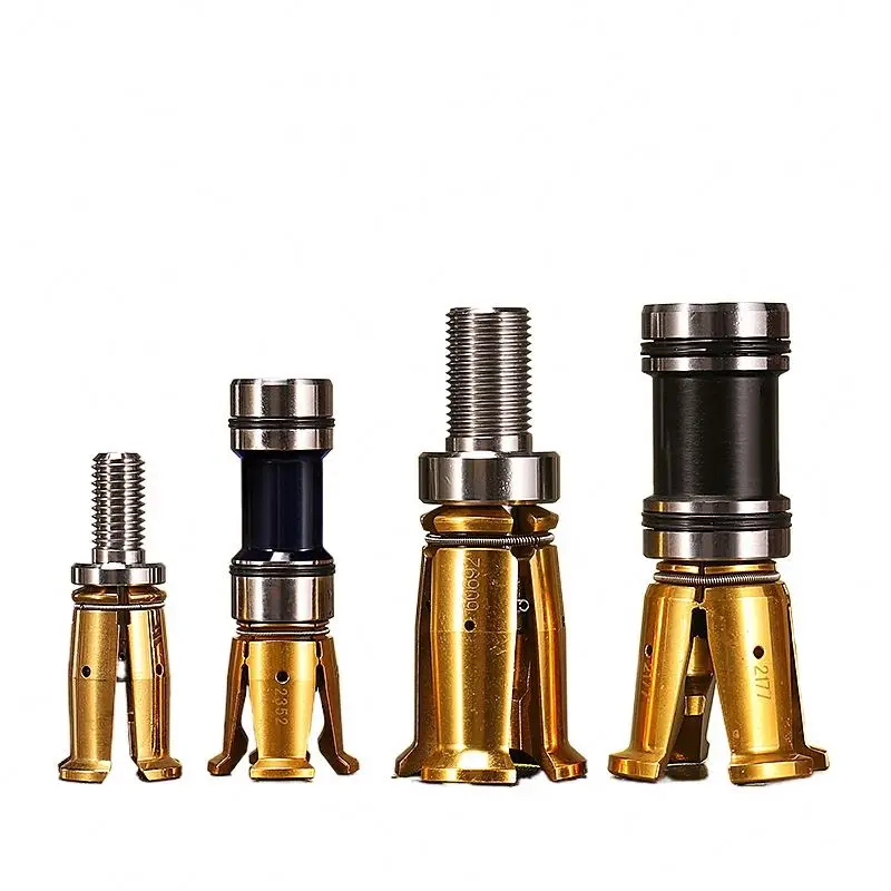
A CNC spindle gripper or claw clamp is a small but safety-critical interface component. A mismatch in taper, thread, pull-stud geometry, shoulder position, or retention behavior can prevent a toolholder from seating correctly or create unacceptable runout. The TEBAK Hoting queue record identifies product ID 1601255939425 with the source wording “BT30-45 H Gripper 4 Petal External Threaded Spindle Claw Clamp CNC Center.” This guide keeps that wording as the product identity and turns every unprovided interface value into a supplier verification item.
The record does not include a product-specific parameter array. It does not confirm the exact BT interface, the meaning of “45,” thread diameter or pitch, material, heat treatment, dimensions, pull-stud compatibility, retention force, runout, balance, spindle model, or service life. A buyer should not release production quantities from the title alone. Approve a dimensioned sample against the actual spindle, drawbar, toolholder, and machining process.
1. What product ID 1601255939425 confirms
Use product ID 1601255939425 on the quotation, drawing, sample label, inspection report, packing list, and purchase order. The source title confirms only the following product wording: BT30-45 H Gripper, 4 Petal External Threaded Spindle Claw Clamp, and CNC Center. It does not provide a model drawing or measurable acceptance values.
| Recorded field | Source value | Procurement action |
|---|---|---|
| Brand | TEBAK | Use TEBAK and product ID 1601255939425 on all records and samples. |
| Product wording | H Gripper / spindle claw clamp | Request an exploded view, assembly drawing, and a clear description of the gripper's position in the spindle retention system. |
| Interface wording | BT30-45 | Confirm whether BT30 is the taper family and what the “45” identifies; do not infer a dimension or model code. |
| Petal count | 4 petal | Confirm four separate gripping segments, their geometry, contact surfaces, spring or actuation method, and replacement arrangement. |
| Thread wording | External threaded | Request major diameter, pitch, thread standard, class, effective length, runout, and mating component. |
| Application wording | CNC center | Confirm spindle manufacturer, spindle model, drawbar design, toolholder family, speed range, and machining duty. |
| Parameters | No parameter array supplied | Require a dimensioned drawing, tolerance table, material data, inspection report, and approved sample before production. |
2. Resolve what “BT30-45” means
“BT30-45” is not enough information for a safe replacement purchase. BT30 may refer to a taper family, while “45” could be a model suffix, a length, a diameter, a spindle series, or another seller-specific identifier. The queue record does not define it. Ask the supplier to write the complete interpretation on the drawing and to mark the same identifier on the sample and package.
Compare the supplied drawing with the spindle manual, original gripper, drawbar, retention knob or pull stud, and toolholder. Check the taper reference, flange position, shoulder contact, internal bore, thread locations, and the axial position reached during drawbar engagement. Do not accept a generic BT30 statement as proof that all BT30 spindle assemblies use the same gripper.
Ask for photos with a scale and a cross-sectional drawing, but use calibrated measurement for approval. If the supplier says “45” is a dimension, request the dimension datum, tolerance, and measurement method. If it is a model code, request the complete model family and compatibility list.
3. Confirm the spindle retention architecture
A gripper can be part of a drawbar retention system rather than a complete toolholder. The buyer needs to know how the four-petal assembly is actuated, where the pull stud is captured, how release occurs, and which surfaces transmit axial force. Request the spindle assembly diagram showing drawbar, Belleville washers or other springs, gripper, spacer, release mechanism, and toolholder interface.
Verify whether the gripper is pulled into a taper, pushed by a sleeve, opened by a release piston, or controlled by another mechanism. Record the released and clamped positions, stroke, spring preload, and any required lubrication. Never install a replacement based only on its outside appearance or number of petals.
During a controlled bench check, confirm that the gripper opens far enough to release the approved pull stud and closes concentrically around it. Check that no petal bottoms out before full engagement and that the drawbar does not reach a false stop. The supplier should approve the exact spindle and pull-stud combination in writing.
4. Thread and mating-part verification
The source title says external threaded, but it does not state the thread standard, diameter, pitch, tolerance class, lead, chamfer, or usable length. Request a thread gauge requirement and a drawing that identifies every threaded surface. Ask whether the thread mates with a retaining sleeve, drawbar part, spacer, nut, or another component.
Do not convert a thread description into a metric or imperial value without evidence. Measure the original component with suitable gauges and compare crest form, pitch, major diameter, minor diameter, shoulder location, and runout. If the mating part is damaged, replace or inspect it before judging a new gripper.
Confirm assembly torque, locking method, thread lubricant, prevailing torque, and service inspection interval. A thread can fit while still positioning the gripper incorrectly. The acceptance drawing should control both thread fit and the axial location of the assembled retention system.
5. Four-petal geometry and load sharing
Four-petal wording identifies a segmented gripping form, but it does not describe petal width, contact radius, opening range, tip profile, synchronization, or load sharing. Request a sectioned drawing with the closed and released positions. Identify which surfaces contact the pull stud and which surfaces contact the spindle or sleeve.
Inspect all four petals for matching geometry, burrs, cracks, uneven wear, and surface damage. Check that the petals move together and that one petal does not carry the load before the others. A partial contact pattern can create local stress and may reduce retention even when the toolholder appears to clamp.
Ask for the allowable wear limit and the replacement rule. Do not use visual symmetry as a substitute for a retention-force or seating test. If the manufacturer has a force test, require the fixture, pull-stud specification, stroke, lubricant condition, and acceptance range.
6. Material, hardness, and surface treatment
No material is supplied in the queue record. Request the exact material grade for the gripper body, petals, threads, pins, springs, and any coating. If multiple materials are used, identify each one in the drawing and inspection plan.
Ask for heat-treatment condition, hardness range, case depth where applicable, surface finish, corrosion protection, and dimensional change after treatment. A hard working surface may resist wear, but excessive brittleness, poor tempering, or a damaged coating can create a safety risk. Do not describe the component as hardened, stainless, alloy steel, or corrosion-resistant until evidence is tied to the quoted product.
Inspect the contact surfaces for grinding marks, pitting, coating flake, raised edges, and embedded abrasive. Ask what lubricant is approved and whether the surface finish is intended for dry, lightly lubricated, or fully lubricated operation. Keep a material certificate separate from a product performance report.
7. Taper, seating, and runout acceptance
Although the source uses BT30 wording, it does not provide taper angle, reference diameter, gauge-line position, face contact, or runout. Request the complete interface drawing and identify the datum used for every critical dimension. The gripper must be evaluated inside the assembled spindle system, not only as a loose part.
Check taper cleanliness, flange contact, toolholder seating, drawbar pull-in, and release. Use a certified test holder or the buyer's approved holder and measure indicated runout at the specified gauge length. Record spindle temperature, lubrication state, clamping cycles, and measurement instrument.
Set the maximum acceptable runout with the machining application. Do not invent a micron limit from a general CNC accessory expectation. The supplier should state its factory inspection limit, while the buyer sets the final assembled-system limit based on the actual spindle and toolholder process.
8. Retention force and drawbar testing
The record contains no retention-force value, drawbar force, spring stack, stroke, or test method. Request a retention-force report for the exact gripper, pull stud, spindle configuration, and lubrication condition. Confirm whether the force is measured statically, dynamically, at room temperature, or after repeated cycles.
Test the assembled system with a calibrated force method and a known pull stud. Record initial force, force after cycling, release behavior, and any change after heat exposure if the spindle process requires it. A gripper that clamps a toolholder at rest may still show poor behavior when the drawbar, springs, or release piston is worn.
Define a controlled rejection rule for incomplete engagement, abnormal release force, slipping, toolholder movement, or failure to release. Do not run a damaged or unverified gripper at production speed merely to see whether it survives.
9. Compatibility with pull studs and toolholders
BT30 toolholders can be paired with different pull-stud geometries and spindle retention systems. The source does not identify the pull-stud standard, thread, angle, head shape, neck, or contact position. Request the exact compatible pull-stud drawing and a compatibility list for the buyer's holders.
Verify the toolholder flange, retention knob, pull-stud head, gripper contact, taper, and drawbar stroke as one system. Test every holder family that will be used in production, including holders from other suppliers. A visually similar pull stud can alter engagement depth or retention force.
Record whether the gripper is compatible with coolant-through tooling, pull studs with different lengths, balanced holders, and automatic tool-changing sequences. If compatibility is limited, print the restriction on the inspection sheet and maintenance instruction.
10. Speed, balance, and CNC operating conditions
The queue record gives no spindle speed, balance grade, permissible rotational speed, vibration limit, or dynamic test result. Do not infer these values from the CNC center wording. Ask for the permitted speed range and whether the gripper assembly is dynamically balanced after machining or only checked statically.
For high-speed use, confirm assembly concentricity, balance condition, lubrication, locking security, and the maximum approved speed for the complete spindle system. A gripper component cannot be given an independent speed claim if the drawbar, toolholder, springs, and spindle impose lower limits.
Run a staged acceptance test: hand rotation, low-speed unloaded rotation, controlled tool-change cycles, and then the buyer's approved speed after all safety gates are satisfied. Monitor vibration, noise, drawbar behavior, toolholder movement, and temperature. Stop on any abnormal signal.
11. Tool-change cycle and service-life validation
No cycle-life value is provided. Request the supplier's cycle test method, load, pull-stud type, lubrication interval, inspection points, and failure criteria. If the component is intended for frequent automatic tool changes, the buyer should test the actual sequence rather than rely on a single manual fit check.
Count clamp and release cycles while checking engagement, retention force, runout, release timing, petal wear, thread condition, spring condition, and toolholder seating. Record the cycle count and the component condition at each inspection interval. Keep replacement criteria specific to the observed failure mode.
Ask for recommended spare parts and whether the four petals are replaced as a set. Confirm whether regrinding, polishing, or field repair is allowed. Unauthorized modification can change the retention geometry and invalidate the original inspection evidence.
12. Installation, lubrication, and maintenance
Request an installation procedure for product ID 1601255939425. It should identify orientation, assembly sequence, torque, locking method, lubrication points, cleaning agent, and safe release procedure. Confirm whether the spindle must be removed or locked out before replacement.
Define a cleanliness standard for taper, threads, petals, drawbar, and pull-stud contact. Chips, dried coolant, abrasive dust, and excess grease can change clamping depth or prevent full seating. Use only the lubricant specified for the spindle system, and record the amount and service interval.
Maintenance checks should include thread damage, petal cracks, contact wear, spring condition, pull-stud condition, drawbar stroke, toolholder seating, runout, and retention force. Do not continue service merely because the component still moves.
13. CNC safety and failure-mode review
A retention component can create a serious hazard if the toolholder is not fully captured. Ask the supplier for warnings covering incomplete engagement, damaged pull studs, incorrect toolholder geometry, over-speed, poor lubrication, and manual work near the spindle.
Review what happens if one petal cracks, a spring loses force, the thread loosens, the release piston sticks, or the drawbar stops short. Define the machine alarm, operator inspection, and lockout response for each credible failure. Do not claim fail-safe, high-speed safe, or production-safe operation without a documented assessment.
Before commissioning, verify emergency-stop behavior, tool-change interlocks, spindle orientation, door interlocks, and safe access. Any test with a new retention component should begin at a controlled condition with no personnel in the hazard zone.
14. Quality inspection plan
The supplier should provide a drawing with critical dimensions, tolerances, datums, thread details, material requirements, hardness where applicable, and surface-finish requirements. The inspection report should identify the serial or lot, instruments, calibration status, inspector, and measured values.
At incoming inspection, verify identity, quantity, packaging, visible damage, thread fit, petal movement, dimensions, and material documents. Then perform the assembled spindle checks: toolholder seating, drawbar stroke, retention force, release, runout, and controlled tool-change cycles.
Separate “fits the spindle” from “meets the production process.” A component can pass dimensional inspection and still fail retention force, dynamic behavior, or cycle-life requirements. Hold the lot until all application-specific acceptance items are signed off.
15. Supplier and company-profile verification
The description names Hengshui Mengshang Trading Co., Ltd. as a professional supplier and describes TEBAK as a brand for design and sales. It also includes a company-profile quality-control statement based on ISO9001 certifications. Treat these as supplier statements that require normal due diligence; they are not product-specific evidence for the gripper.
Request the legal entity on the quotation, invoice, packing list, warranty, and inspection report. Confirm whether the supplier manufactures the gripper, designs it, resells it, or coordinates production. Ask for the actual inspection location, responsible engineer, traceability method, spare-part responsibility, and change-notification process.
If an ISO9001 certificate is presented, verify the certificate holder, scope, issuer, validity, and entity match. Keep a management-system certificate separate from the material, geometry, retention-force, runout, balance, and cycle-life evidence for product ID 1601255939425.
16. RFQ checklist for product ID 1601255939425
- Confirm the exact TEBAK model and product ID 1601255939425 on the quotation and sample.
- Explain the complete meaning of BT30-45 and provide an interface drawing with datums.
- Confirm the four-petal geometry, opening range, contact surfaces, actuation, and replacement method.
- Confirm all external thread dimensions, pitch, standard, tolerance class, effective length, and mating component.
- Identify the material, heat treatment, hardness, coating, surface finish, corrosion protection, and material evidence.
- Provide taper, shoulder, flange, bore, axial-position, and runout dimensions with tolerances.
- Provide compatible spindle manufacturers, spindle models, drawbars, pull studs, and BT30 toolholders.
- Provide retention force, drawbar stroke, release force, spring condition, and test methods.
- State permitted rotational speed, balance condition, vibration limit, lubrication, and dynamic test scope if applicable.
- Provide cycle-life data, inspection intervals, wear limits, replacement rules, and spare-part availability.
- Provide installation, torque, cleaning, lubrication, storage, lockout, and maintenance instructions.
- Provide incoming and assembled-system inspection reports, including instrument and calibration details.
- Define acceptance tests for seating, retention, release, runout, tool change, and staged rotation.
- Provide final packing list, individual protection, lot traceability, warranty, change control, and delivery terms.
- If ISO9001 is claimed, provide holder, scope, issuer, validity, and entity match; do not treat it as product certification.
17. Comparing replacement grippers
Compare offers by verified interface geometry, mating pull-stud compatibility, retention force, release behavior, assembled runout, material evidence, surface finish, speed and balance limits, cycle-life data, service instructions, traceability, and warranty. Do not rank a gripper by BT30 wording, four-petal appearance, or a low unit price alone.
Normalize each quotation into the gripper, springs or related parts, required pull stud, spindle-specific spacers, lubrication, inspection report, installation service, spare set, and warranty. A lower price may exclude the drawing, matched mating parts, inspection fixtures, or the spare components required for planned maintenance.
Keep company profile information separate from component evidence. TEBAK and Hengshui Mengshang Trading Co., Ltd. can be reviewed during supplier qualification, but the exact product 1601255939425 must still pass the buyer's spindle compatibility and assembled-system safety checks.
18. Purchase-order wording
A purchase order can state: “TEBAK BT30-45 H Gripper, 4 Petal External Threaded Spindle Claw Clamp for CNC Center, product ID 1601255939425, supplied strictly to the approved drawing, material and treatment specification, thread definition, compatible spindle and pull-stud list, retention-force report, assembled runout limit, installation procedure, inspection report, packing list, and warranty.”
Add the confirmed meaning of BT30-45, every critical dimension and tolerance, thread standard, petal geometry, force and stroke, speed and balance limits, cycle-life requirement, spare-part rule, lot traceability, change-notification requirement, and the final acceptance test. State that title wording alone does not establish compatibility or production safety.
19. Frequently asked questions
What does the source record identify?
It identifies TEBAK product 1601255939425 with the wording BT30-45 H Gripper, 4 Petal External Threaded Spindle Claw Clamp, CNC Center.
Does BT30-45 fully define the interface?
No. Confirm the taper family, the meaning of 45, dimensions, datums, thread, pull-stud geometry, and spindle compatibility from a drawing.
Does four-petal wording prove the gripper fits my spindle?
No. Petal count does not establish geometry, opening range, actuation, retention force, or compatibility.
Is the material specified?
No product material is supplied in the queue record. Request material grade, treatment, hardness, finish, and evidence.
Can the gripper be rated for high-speed CNC use from the title?
No. Request speed, balance, vibration, lubrication, and assembled-system test conditions before approval.
Does the company ISO9001 statement certify this gripper?
No. Verify any management-system certificate separately from the gripper's geometry, material, retention, runout, and cycle evidence.
Supplier inquiry template
Hello, we are evaluating TEBAK product 1601255939425, described as a BT30-45 H Gripper, 4 Petal External Threaded Spindle Claw Clamp for a CNC Center. Please explain the complete meaning of BT30-45 and send the dimensioned assembly and section drawings. Confirm every thread, mating part, petal geometry, material, heat treatment, hardness, surface finish, compatible spindle and pull-stud, retention force, drawbar stroke, release behavior, runout, speed and balance limits, lubrication, cycle life, wear limit, inspection method, packing, spare parts, and warranty. Please provide an assembled sample test report using our spindle, drawbar, pull stud, and approved BT30 toolholder if possible. The company profile names Hengshui Mengshang Trading Co., Ltd. and mentions ISO9001-based quality-control standards; please provide the legal entity and certificate scope and validity while keeping company-level claims separate from product evidence. Send the complete drawing, datasheet, manual, inspection report, and change-control terms before production.
Key specifications
- Brand
- TEBAK
- Product ID
- 1601255939425
- Source product wording
- BT30-45 H Gripper, 4 Petal External Threaded Spindle Claw Clamp, CNC Center
- Product form
- Gripper / spindle claw clamp wording; exact assembly and interface require confirmation
- Interface wording
- BT30-45; confirm whether this denotes BT30 tooling, a 45 mm dimension, a model code, or another interface reference
- Petal count
- 4 petal wording in the source title
- Thread wording
- External threaded wording in the source title
- Application wording
- CNC center
- Product parameters
- No product-specific parameter array was supplied in the queue record
- Company profile
- Hengshui Mengshang Trading Co., Ltd.; TEBAK is described as its brand for design and sales
- Unspecified buyer-critical fields
- Material, thread size and pitch, dimensions, pull-stud interface, retention force, runout, hardness, compatibility, load rating, service life, packing, warranty, and compliance documents
Frequently asked questions
- What does the source record identify?
- TEBAK product 1601255939425 is described as a BT30-45 H Gripper, 4 Petal External Threaded Spindle Claw Clamp for a CNC Center.
- Does BT30-45 fully define the interface?
- No. Confirm the taper, meaning of 45, dimensions, datums, thread, pull-stud geometry, and spindle compatibility from a drawing.
- Does four-petal wording prove the gripper fits my spindle?
- No. Petal count does not establish geometry, opening range, actuation, retention force, or compatibility.
- Is the material specified?
- No product material is supplied in the queue record. Request material grade, treatment, hardness, finish, and evidence.
- Can the gripper be rated for high-speed CNC use from the title?
- No. Request speed, balance, vibration, lubrication, and assembled-system test conditions before approval.
- Does the company ISO9001 statement certify this gripper?
- No. Verify the management-system certificate separately from the gripper's geometry, material, retention, runout, and cycle evidence.