
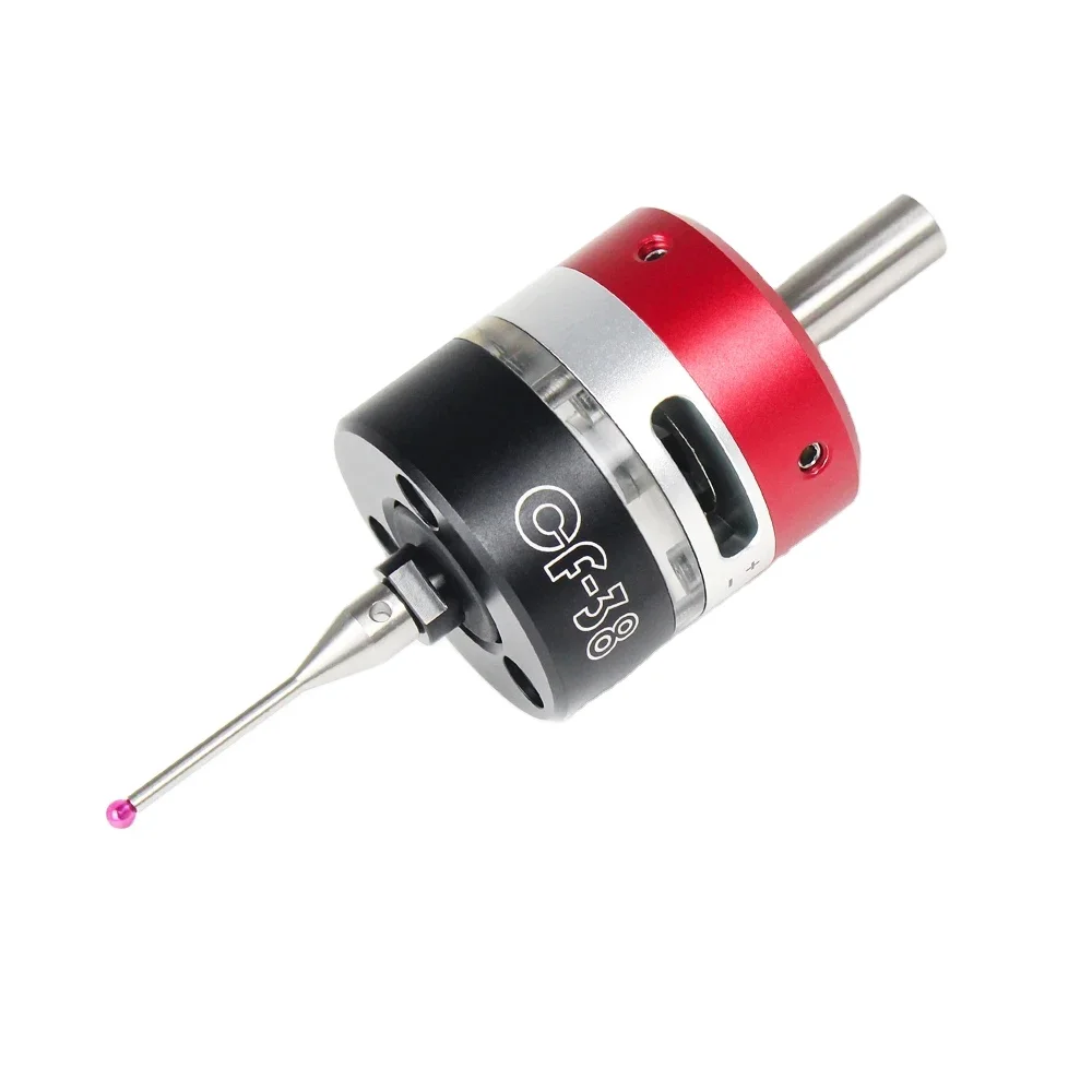
A CNC edge finder should be qualified as a complete measurement tool, not selected only from a product title or a probe photograph. The TEBAK Hoting queue record identifies product ID 1601289408152 as a “Trigger 3D Edge Finder” with item model number CF-38. The listing title also uses machining-center, CNC milling-machine, three-coordinate precision probe, centring rod, and tool-setter wording.
The source provides two safety-stroke descriptions: X/Y plane ±20° and Z direction +2.5mm. It specifies one CR1632 3V button battery and says the product can measure insulating material. It also provides handling instructions: hold the probe seat at the wrench slot during installation so the internal parts do not rotate, and install a replacement battery according to the +/- mark. Accuracy, repeatability, runout, trigger force, shank interface, and calibration data are not supplied. This guide keeps those limits visible for B2B sourcing.
1. What product ID 1601289408152 confirms
Use product ID 1601289408152 on the quotation, probe label, inspection record, packing list, and purchase order. The source record confirms the CF-38 model wording and operating instructions, but it does not provide the engineering drawing required to prove compatibility with a particular CNC spindle or tool holder.
| Recorded field | Source value | Buyer action |
|---|---|---|
| Brand | TEBAK | Use TEBAK and product ID 1601289408152 on all commercial and technical records. |
| Product name | Trigger 3D Edge Finder | Confirm the exact CF-38 assembly, included probe, battery, case, and accessories. |
| Model | CF-38 | Request model drawing, revision, serial or lot traceability, and firmware or calibration record if applicable. |
| Probe safety stroke | X/Y plane ±20°; Z direction +2.5mm | Confirm the reference axis, neutral position, measuring direction, stop condition, and allowable speed. |
| Power supply | CR1632 3V button battery x 1 | Confirm approved battery chemistry, polarity, holder, replacement interval, and low-battery behavior. |
| Material wording | Measurable insulating material | Define which insulating materials, surfaces, conditions, and measurement method are covered. |
| Installation | Hold the probe seat at the wrench slot | Include the handling step in the work instruction to prevent internal rotation and damage. |
2. Resolve the product type and measurement role
The title combines edge finder, precision probe, centring rod, and tool setter wording. These functions can have different interfaces and acceptance tests. Ask the supplier to state whether CF-38 is intended for manual edge finding, automatic CNC probing, tool-length setting, workpiece centring, or a combination of these functions.
Request a sequence diagram showing how the trigger signal is generated, detected, and displayed or transferred to the CNC control. Confirm whether the tool is a standalone visual or audible edge finder, a probe that interfaces with a machine input, or a sensor used with a separate receiver. Do not infer automatic probing capability from the word “3D.”
Define the buying requirement before comparing offers. A manual setup tool may be suitable for an operator's edge-finding process but unsuitable for closed-loop automatic measurement. An automatic probe may require a receiver, interface, macro, post-processor, or control input that is not included in the product price.
3. Spindle interface and mechanical fit
The queue record does not provide shank diameter, taper, thread, collet requirement, holder type, overall length, probe diameter, or gauge length. Request a dimensioned drawing for the CF-38 assembly and the recommended tool-holder configuration.
Confirm whether the probe is installed directly in a collet, chuck, BT/ISO/HSK holder, manual spindle, or another fixture. Check the holder's runout, gripping range, balance, clearance, and tool-change behavior. A 3D edge finder cannot be accepted into a CNC machining center without a controlled interface between the probe and spindle.
Measure the actual machine's spindle taper and tool-holder system. Confirm clearance to the workpiece, vise, fixture, coolant nozzle, and machine enclosure. Check the probe's body, stylus, and safety-stroke envelope at the required measurement position before powering the machine.
4. X/Y safety stroke: ±20°
The source states probe safety stroke in the X/Y plane as ±20°. It does not state whether this is an angular deflection, a mechanical travel, or a drawing notation. Preserve the source wording and ask the supplier to define the angle reference, neutral position, and maximum permitted deflection.
Confirm whether ±20° applies equally in X and Y, whether the probe can be deflected diagonally, and whether the safety stroke is a limit rather than a recommended measuring range. Request a section drawing showing the stylus axis, pivot, stop, and allowed deflection zone.
Define a safe approach protocol. Use a low approach speed, stop immediately after trigger or contact, and retract before the probe reaches its mechanical limit. Do not convert the angular wording into a linear displacement without the probe geometry and measurement point.
5. Z safety direction: +2.5mm
The source lists Z direction +2.5mm. It does not say whether this is axial compression, positive-axis travel, a safety stop, or a maximum measuring stroke. Ask the supplier to mark the Z reference and sign convention on the drawing.
Confirm the neutral height, trigger point, maximum safe compression, return mechanism, and acceptable approach direction. A tool setter or edge probe can be damaged if the machine continues moving after a trigger. Configure the CNC macro or operator procedure with a controlled stop and retraction distance that the supplier approves.
Test the Z stroke with a non-production fixture before the first workpiece. Record the direction, approach speed, trigger signal, stopping distance, overshoot, return position, and any contact damage. Do not treat +2.5mm as an accuracy or repeatability value.
6. Battery and power management
CF-38 is specified with one CR1632 3V button battery. Request the approved battery brand or chemistry, holder drawing, polarity marking, current consumption, storage rule, expected service interval, and low-battery indication or failure behavior.
Follow the source replacement procedure: remove the battery plug, remove the battery with tweezers, install a new battery according to the +/- mark on the side, and plug the battery plug tightly. Keep the battery replacement instruction with the machine's maintenance documentation. Do not use a metal tool that can short the cell or damage the holder unless the supplier explicitly approves it.
Test the probe after battery replacement. Verify trigger response, signal or indicator, return behavior, and any calibration or zero procedure. Record the battery lot and replacement date for a production tool. Confirm storage conditions and remove the battery during long-term storage if the supplier requires it.
7. Installation procedure and wrench slot
The source warns that the probe interface has a wrench slot and that the probe seat must be held during installation. If the seat is allowed to rotate, internal parts may be damaged. This is a product-specific handling instruction and should appear in the buyer's work instruction.
Request the correct wrench size, tightening torque, installation direction, thread or interface drawing, and any locking or sealing requirement. Hold the probe seat at the designated wrench slot while tightening the mating part. Do not clamp the probe body, stylus, or sensor housing at an unapproved location.
After installation, inspect the probe for free movement, stylus alignment, trigger response, and visible damage. Measure runout in the selected holder and record the result. If the probe has been rotated or over-tightened accidentally, quarantine it until the supplier or an approved inspection method confirms that the internal mechanism remains functional.
8. Measuring insulating material
The source states “measurable insulating material.” It does not define the material types, surface condition, probe mode, contact force, electrical method, or measurement limits. Ask the supplier to explain what this statement means for the CF-38 measurement process.
Identify the buyer's material: plastic, composite, coated surface, ceramic, painted part, or another non-conductive workpiece. Confirm whether the probe relies on mechanical trigger, electrical continuity, optical detection, or a separate sensing method. Do not claim that every insulating material is measurable from the short source phrase.
Test representative materials with the buyer's surface finish, temperature, coolant residue, and geometry. Record false triggers, missed triggers, contact marks, repeatability, and the required cleaning procedure. If a conductive reference is required for calibration or machine input, include it in the setup instructions.
9. Accuracy, repeatability, and runout
No measurement accuracy, repeatability, concentricity, runout, trigger force, resolution, or calibration interval is listed. These values must be requested before the CF-38 is used for a tolerance-critical CNC process.
Ask for the supplier's definitions: edge-finding error, trigger repeatability, stylus repeatability, return repeatability, axial runout, radial runout, and temperature condition. Request test data for the exact model or lot, not a generic statement about a product family.
At incoming inspection, measure runout in the approved holder and test repeated contact on a calibrated reference. Record machine axis, approach direction, speed, holder, battery state, temperature, and contact surface. Separate probe error from machine backlash, spindle runout, holder error, workpiece error, and operator reaction time.
10. CNC control and signal integration
The source does not specify an electrical output, receiver, cable, interface, voltage, signal polarity, connector, macro, or control compatibility. Ask whether CF-38 produces a visual indication only or a machine-readable trigger signal.
If an automatic input is supplied, request a wiring diagram with signal type, voltage, current, normally open or normally closed state, debounce behavior, response time, and emergency-stop relationship. Confirm whether the CNC control needs a dedicated probing input, receiver, relay, or interface module.
Test the complete chain from physical contact to machine response. Verify that the machine stops or retracts safely, that an open cable or low battery does not create an unsafe false-ready state, and that the probing macro records the correct axis and direction. Never connect an unknown probe output directly to a controller input.
11. Approach speed and safety programming
The queue record does not provide a maximum measuring speed or recommended approach speed. Request the speed limits for manual and automatic use, including rapid approach, final approach, retract, and repeated probing.
Write a safe probing sequence with clearance, low-speed final approach, trigger detection, immediate stop, controlled retract, timeout, and alarm handling. Include a maximum travel limit below the stated safety stroke and a check for a missing or already-triggered signal.
Run dry tests with the spindle stopped and the tool away from the workpiece. Then test on a sacrificial reference before production. Confirm that an incorrect axis sign, coordinate offset, holder length, or macro parameter cannot drive the probe into the table or fixture.
12. Calibration and reference procedure
Ask for the supplier's calibration procedure, reference artifact, zero definition, frequency, and records. The product description names CF-38 but does not provide calibration data or a certificate.
Define the buyer's reference edge, face, sphere, ring, or gauge. Verify the probe after battery replacement, holder change, accidental overload, stylus replacement, unusual temperature, or a failed measurement. Store calibration results with the probe product ID and serial or lot number.
Do not use an unverified probe to establish machine coordinates for a high-value production run. If the probe is used for manual setup only, document the operator reading method and the expected human-response uncertainty separately from the probe's mechanical repeatability.
13. Stylus, probe body, and replaceable parts
The source does not list stylus diameter, length, material, thread, replaceability, spare parts, or protective cap. Request an exploded view and parts list for the CF-38.
Confirm how to inspect a bent stylus, damaged tip, loose probe seat, cracked housing, worn interface, or contaminated contact. Ask whether a stylus can be replaced by the buyer and whether replacement changes calibration. Keep spare parts identified by the exact CF-38 model and revision.
Protect the probe during tool changes and storage. Use the supplier-approved case or cap and prevent the stylus from carrying the weight of the assembly. Do not store the tool where chips, coolant, magnets, heat, or impact can affect the trigger mechanism.
14. Environmental and workshop conditions
Operating temperature, storage temperature, humidity, coolant resistance, dust protection, vibration, and ingress rating are not supplied. Request environmental limits for the exact CF-38 assembly and battery.
Test the probe under the buyer's real workshop conditions, including coolant mist, chips, oil film, gloves, lighting, and temperature changes. Define cleaning materials and drying procedure. Avoid introducing liquid into the battery plug or probe interface.
Keep the probe clean before each measurement. A chip between the stylus and workpiece can create a false edge, while a damaged or contaminated wrench interface can encourage incorrect installation. Record environmental restrictions in the operator checklist.
15. Incoming inspection and acceptance test
At receipt, verify product ID 1601289408152, model CF-38, battery presence, labels, probe movement, wrench slot, battery plug, stylus condition, holder interface, case, and manuals. Photograph the package and probe before use.
Run a basic functional test: install the battery, verify polarity and plug engagement, mount the probe without rotating the seat, check trigger response in X/Y and Z directions, inspect return behavior, and measure holder runout. Do not exceed the supplier-defined safety stroke.
Then run the buyer's representative measurement test on a calibrated reference and an insulating material if that function is required. Record approach speed, contact direction, result repeatability, battery state, machine input, and any visible mark. Acceptance should be based on the buyer's process requirement, not only on a product title.
16. Supplier and company-profile verification
The description identifies Hengshui Mengshang Trading Co., Ltd. and describes TEBAK as its brand for design and sales. Treat these as supplier-profile statements requiring normal due diligence. They do not prove CF-38 accuracy, interface compatibility, or certification.
Request the legal entity on the quotation, invoice, packing list, warranty, and calibration or inspection record. Confirm whether the supplier manufactures, designs, distributes, or integrates the probe. Ask for the responsible technical contact, replacement route, spare-parts policy, and change-notification process.
If the supplier presents a management-system certificate, verify its holder, scope, issuer, validity, and entity match. Keep company-level evidence separate from CF-38 mechanical, electrical, battery, measurement, and safety evidence.
17. RFQ checklist for product ID 1601289408152
- Confirm TEBAK product ID 1601289408152, model CF-38, revision, serial or lot traceability, and included parts.
- Define whether the tool is manual edge finder, automatic CNC probe, tool setter, centring rod, or a combination.
- Provide shank diameter, taper, thread, holder requirement, overall length, probe diameter, gauge length, and drawing.
- Clarify X/Y plane ±20° and Z direction +2.5mm with axis reference, neutral position, stroke type, and speed limit.
- Confirm CR1632 3V battery type, polarity, holder, current, low-battery behavior, storage, and replacement interval.
- Explain “measurable insulating material,” including material types, sensing method, surface limits, and test evidence.
- Provide accuracy, repeatability, trigger force, resolution, radial and axial runout, calibration method, and interval.
- Provide electrical output, receiver, cable, connector, voltage, polarity, interface module, and CNC control compatibility.
- Provide installation wrench size, torque, seat-retention method, interface thread, and damage-prevention instructions.
- Provide stylus diameter, length, material, replacement method, spare parts, protective cap, and case.
- Define automatic probing macro, approach speed, retract, timeout, alarm, low-battery, and emergency behavior.
- Provide temperature, humidity, coolant, dust, vibration, ingress, cleaning, and storage requirements.
- Perform incoming inspection and a representative reference test before production release.
- Provide manuals, calibration or inspection report, packing list, warranty, service response, and change control.
- If company certifications are claimed, provide certificate holder, scope, issuer, validity, and entity match; do not treat them as probe certification.
18. Comparing edge-finder offers
Compare offers by exact function, CF-38 configuration, spindle interface, safety stroke, accuracy, repeatability, runout, trigger force, signal integration, battery behavior, calibration, stylus service, environmental limits, test evidence, spare parts, traceability, and warranty. Do not rank a probe by the word “precision” alone.
Normalize each quotation into probe body, stylus, holder or shank, battery, wrench, receiver, cable, interface module, software or macro, case, calibration report, spare parts, training, packing, and warranty. A low price may cover only the probe body and exclude the receiver, machine interface, holder, or calibration support needed for automatic CNC use.
Keep product claims and supplier claims separate. TEBAK and Hengshui Mengshang Trading Co., Ltd. can be assessed during supplier qualification, but product ID 1601289408152 must still pass the buyer's interface, battery, trigger, stroke, measurement, and safety tests.
19. Purchase-order wording
A purchase order can state: “TEBAK Trigger 3D Edge Finder, model CF-38, product ID 1601289408152, for the approved manual or automatic CNC measurement application, with the approved spindle interface, X/Y safety stroke ±20° as defined, Z direction +2.5mm as defined, one CR1632 3V battery, installation wrench instruction, battery replacement instruction, inspection or calibration record, accessories, packing list, and warranty.”
Add the exact shank and holder, accuracy, repeatability, runout, signal interface, macro, battery behavior, insulating-material test, environmental limits, acceptance test, spare parts, and rejection criteria. State that title wording alone does not establish automatic probing capability.
20. Frequently asked questions
What is the CF-38 product?
The source identifies it as a Trigger 3D Edge Finder and uses machining-center, CNC milling-machine, three-coordinate precision probe, centring rod, and tool-setter wording.
What safety stroke is listed?
The source lists X/Y plane ±20° and Z direction +2.5mm. Confirm the axis reference, stroke type, and safe operating limit before use.
What battery does it use?
One CR1632 3V button battery is listed. Confirm the approved cell, polarity, holder, low-battery behavior, and replacement interval.
Can it automatically measure on every CNC?
The source does not provide a control interface, receiver, cable, macro, or compatibility list. Confirm the complete mechanical and electrical system for the target CNC.
Can it measure insulating materials?
The source says measurable insulating material but provides no method or material limits. Request the sensing principle and test the buyer's actual surfaces.
Why must the probe seat be held during installation?
The source states that a wrench slot should be used to prevent the probe seat from rotating, because rotation can damage internal parts.
Supplier inquiry template
Hello, we are evaluating TEBAK product 1601289408152, model CF-38 Trigger 3D Edge Finder. Please confirm whether the supplied tool is intended for manual edge finding, automatic CNC probing, tool setting, centring, or a combination. Provide the mechanical drawing with shank, taper, thread, holder, probe, gauge length, and runout. Please define X/Y plane ±20° and Z direction +2.5mm, including reference, neutral position, stroke type, approach speed, and safe limit. Confirm the CR1632 3V battery, polarity, holder, low-battery behavior, and replacement procedure. Explain the measurable-insulating-material claim and provide accuracy, repeatability, trigger force, sensing method, CNC interface, receiver, cable, macro, calibration, environmental, cleaning, spare-part, inspection, packing, and warranty information. Please include the wrench-slot installation instruction because the probe seat must be held to prevent internal damage. Test the probe with our holder, CNC input, reference edge, and insulating material before production approval.
Key specifications
- Brand
- TEBAK
- Product ID
- 1601289408152
- Product name
- Trigger 3D Edge Finder
- Item model number
- CF-38
- Title wording
- 3D Edge Finder for machining center / CNC milling machine; three-coordinate precision probe centring rod tool setter wording
- Probe safety stroke
- X/Y plane ±20°; Z direction +2.5mm
- Power supply
- One CR1632 3V button battery
- Material wording
- The source states measurable insulating material; confirm the exact material scope and measurement limitation
- Installation instruction
- Hold the probe seat at the wrench slot during installation to prevent rotation and internal damage
- Battery instruction
- Remove the battery plug, remove the battery with tweezers, install according to the +/- mark, and plug the battery plug tightly
- Unspecified buyer-critical fields
- Accuracy, repeatability, runout, trigger force, spindle interface, shank size, working speed, temperature range, protection, calibration, compatibility, packing, warranty, and compliance documents
- Company profile
- Hengshui Mengshang Trading Co., Ltd.; TEBAK is described as its brand for design and sales
Frequently asked questions
- What is the CF-38 product?
- The source identifies it as a Trigger 3D Edge Finder and uses machining-center, CNC milling-machine, three-coordinate precision probe, centring rod, and tool-setter wording.
- What safety stroke is listed?
- The source lists X/Y plane ±20° and Z direction +2.5mm. Confirm the axis reference, stroke type, and safe operating limit before use.
- What battery does it use?
- One CR1632 3V button battery is listed. Confirm the approved cell, polarity, holder, low-battery behavior, and replacement interval.
- Can it automatically measure on every CNC?
- The source does not provide a control interface, receiver, cable, macro, or compatibility list. Confirm the complete mechanical and electrical system for the target CNC.
- Can it measure insulating materials?
- The source says measurable insulating material but provides no method or material limits. Request the sensing principle and test the buyer's actual surfaces.
- Why must the probe seat be held during installation?
- The source states that a wrench slot should be used to prevent the probe seat from rotating, because rotation can damage internal parts.