
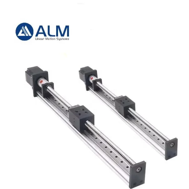
One product described five different ways
The title reads: Customized Ball Screw Cnc Machine Linear Motion Guide Micro Linear Module With Stepper Motor Linear Actuator Single Axis Robot. That is a single item labelled as a ball screw module, a linear guide, a micro linear module, a linear actuator and a single-axis robot in one line. In the trade those are not synonyms. A linear guide carries load. A module adds the drive. An actuator usually includes motor and controls. A single-axis robot normally means a closed-loop positioning axis with its own controller and enclosure. The parameter block does not resolve which one this is.
What it does resolve is four numbers a buyer can actually work with: a maximum speed of 1,250 mm/sec, a repeatability of plus or minus 0.01 mm, a stroke range of 50 to 1,000 mm, and ball screw accuracy offered as C5, C7 or C3. Those four numbers are also where the trouble starts, because at least three of them cannot hold simultaneously.
The two numbers that decide everything are missing
Accuracy grade is published. The screw diameter and the lead are not. For a positioning module those two numbers, far more than the grade, decide what the axis can do:
| Missing number | What it actually controls |
|---|---|
| Screw diameter | Critical speed (how fast it can spin before whipping), axial rigidity, load capacity |
| Screw lead | Speed at a given motor rpm, resolution per step, thrust per unit torque |
Without them, 1,250 mm/sec is a claim with no denominator. Two modules from the same catalogue, on the same motor, can differ by a factor of four in speed because one has a 5 mm lead and the other a 20 mm lead. They look identical in a photograph and are not the same machine.
1,250 mm/sec is 75 metres per minute
Converted: 1,250 mm/sec equals 75,000 mm/min. A screw advances one lead per revolution, so the required motor speed is 75,000 divided by the lead.
| Lead | rpm needed for 1,250 mm/sec | Feasible on a screw of this class |
|---|---|---|
| 5 mm | 15,000 | No |
| 10 mm | 7,500 | No |
| 16 mm | 4,688 | Marginal at best |
| 20 mm | 3,750 | Only at short stroke |
| 25 mm | 3,000 | Yes, with a servo |
| 32 mm | 2,344 | Yes |
| 40 mm | 1,875 | Yes, but see the helix angle below |
The first three rows are outside the physical range of a ball screw in this size, regardless of what the catalogue says. The headline speed therefore does not describe the standard configuration. It describes one configuration, and the listing never says which.
Critical speed: the long stroke is the constraint
A ball screw is a long slender shaft in compression and rotation. Above a certain speed it whips, and the limit falls with the square of the unsupported length — double the stroke and the allowable speed drops by four.
Using the standard critical-speed relation for steel (E = 2.06 × 10⁵ N/mm2, density 7.85 × 10⁻⁶ kg/mm3), one end fixed and one supported, and taking 80 percent of the theoretical value as a working limit:
| Screw diameter | Stroke (unsupported length) | Theoretical critical speed | Working limit at 80 percent |
|---|---|---|---|
| 12 mm | 1,000 mm | 2,263 rpm | 1,810 rpm |
| 16 mm | 1,000 mm | 3,017 rpm | 2,414 rpm |
| 16 mm | 500 mm | 12,068 rpm | 9,654 rpm |
A second limit then applies at short strokes: the DN value, speed times diameter, conventionally 70,000 for a standard rolled screw. That caps a 16 mm screw near 4,375 rpm and a 12 mm screw near 5,833 rpm however favourable the critical speed looks.
Put the two together. To reach 1,250 mm/sec at the full 1,000 mm stroke on a 16 mm screw you need roughly 31 mm of lead — call it 32 mm, because that is what catalogues stock. At 500 mm stroke, where 3,750 rpm is permitted, a 20 mm lead is enough. So the headline speed belongs to the short end of the stroke range with a large lead and a light load. It is not available at the long end with a 5, 10 or 16 mm lead, and the listing does not say so.
A 32 mm lead on a 16 mm screw is a 32 degree helix
Lead angle is arctan of lead divided by pi times diameter. For a 16 mm shaft:
| Lead | Lead angle | Practical consequence |
|---|---|---|
| 5 mm | 5.7 degrees | Self-locking in most orientations |
| 10 mm | 11.3 degrees | Marginal; check orientation |
| 20 mm | 21.7 degrees | Backdrivable |
| 32 mm | 32.5 degrees | Backdrivable, needs a brake on any non-horizontal axis |
At 32 degrees the screw behaves less like a machine-tool lead screw and more like a screw conveyor: high efficiency, high reverse efficiency. With the motor unpowered, a vertical or inclined axis can run down under its own load. A holding brake becomes mandatory, and the listing offers neither a brake nor a statement of which orientations the module is rated for.
0.01 mm is exactly one microstep at that lead
A 1.8 degree stepper has 200 full steps per revolution. Divide the lead by 200 for full-step resolution, then by the microstep setting.
| Lead | mm per full step | mm per microstep at 16x |
|---|---|---|
| 5 mm | 0.0250 | 0.0016 |
| 10 mm | 0.0500 | 0.0031 |
| 20 mm | 0.1000 | 0.0063 |
| 32 mm | 0.1600 | 0.0100 |
Row four is the lead the speed demands, and 0.0100 mm is the stated repeatability. The two headline figures are the same number seen twice: the axis repeats to one microstep. That is not a lie, but it leaves nothing at all for screw lead error, nut backlash, coupling wind-up, thermal growth, or encoder resolution — because there is no encoder. This is an open-loop stepper.
Microstepping also does not buy accuracy. Detent torque and friction mean the practical error of a microstepped stepper is commonly 3 to 5 percent of a full step, which at a 32 mm lead is 0.005 to 0.008 mm before anything else is counted. The full step is the real unit of resolution; the microstep is a smoothness setting.
Accuracy and repeatability are different numbers, and the difference is expensive
This is the most costly misunderstanding in the whole listing. Ball screw accuracy grades describe lead error over a defined length — they say nothing about how tightly the axis returns to a commanded point.
| Grade | Lead error per 300 mm | Scaled over 1,000 mm |
|---|---|---|
| C7 (rolled) | 0.050 mm | 0.167 mm |
| C5 | 0.023 mm | 0.077 mm |
| C3 (ground) | 0.008 mm | 0.027 mm |
Read it as: a C7 screw can repeat to 0.01 mm all day long and still leave the carriage 0.17 mm from where you commanded it after a metre of travel. If your drawing says positional accuracy 0.01 mm and the quotation says C7, the quotation is not wrong — it is answering a different question. For 0.01 mm absolute you need C5 or better, or a linear scale closing the loop on the carriage rather than on the motor.
The listing offers all three grades as though they were a colour choice. They are not. C3 requires a ground screw and a preloaded nut, costs several times C7, and changes the lead time — see the contradiction below.
A stepper will not deliver 3,750 rpm with useful torque
Steppers lose torque with speed. The holding torque on the label is measured at zero rpm. A NEMA23 frame motor with roughly 3 N·m holding typically produces 0.3 to 0.5 N·m around 3,000 rpm on a 48 V drive, and less above it.
The torque the move requires is usually not the problem. Accelerating a 5 kg carriage at 10 m/s2 needs about 50 N, which on a 20 mm lead at 90 percent efficiency is only 0.18 N·m. The binding constraint is what the motor can still produce at the speed that lead demands. At 3,750 rpm a stepper is close to the end of its usable range, and the margin disappears into friction and belt or coupling losses.
If the axis genuinely has to run 1,250 mm/sec over a 1 m stroke, the honest configuration is a servo driving a 32 mm lead, or a linear motor. The listing puts a stepper and a 1,250 mm/sec figure in the same sentence without reconciling them, and that reconciliation is the buyer's job.
Stopping from 1,250 mm/sec costs 78 mm of travel
Decelerating at 10 m/s2 from 1,250 mm/sec takes v2/2a = 78 mm. Every move shorter than about 150 mm therefore never reaches the headline speed at all: it is a triangular profile that accelerates to a lower peak and comes straight back down. On the 50 mm stroke version, maximum speed is set by the stroke, not by the screw.
Settling is the other half of the story. Arriving at plus or minus 0.01 mm after a 1.25 m/sec move means waiting for the structure to stop ringing and for the in-position signal to be issued. No settling time, no stiffness and no damping figure appears anywhere in the listing. That is normal for this class of listing, and it is exactly why the number has to be agreed in writing before the order.
Stroke is not length
The block gives stroke 50 to 1,000 mm and length as customised. Overall length is stroke plus the carriage, two end blocks, the bearing supports and the motor. For a module of this class, add 250 to 400 mm.
That matters twice. Mechanically, because a 1,000 mm stroke module needs about 1,300 mm of clear space plus room for the cable carrier to fold. Commercially, because freight is billed on volume and length: a 1,300 mm extrusion is a long item, and its volumetric weight will exceed its actual weight on every shipment.
Four statements in the parameter block contradict each other
Weight 0.8 kg. A module with a 1,000 mm stroke cannot weigh 0.8 kg. An aluminium extrusion of this class runs 2.5 to 3 kg per metre before the carriage, rails, screw and motor are fitted. 0.8 kg is credible only at the very shortest stroke, and is most likely a template default left in place.
Core components lists both a lead screw and a ball screw. These are different transmissions with different efficiency, backlash and price. Either the family genuinely contains both and the buyer must choose, or the field was filled in without checking. Ask which one the quoted price covers, and ask for the part number of the screw.
Lead time 5 to 10 days alongside a C3 option. C3 needs a ground screw, and ground screws in this size are typically quoted at 20 to 30 days. A 5 to 10 day promise is consistent with rolled C7 stock from a shelf, not with C3. One of the two statements is decorative, and it is worth knowing which before you promise a delivery date to your own customer.
Marketing type: new product 2020. The listing has been live for six years without revision. That is the most likely explanation for the template weight, the unreconciled speed figure and the 2020 date still sitting in the field.
What the application list implies but does not supply
Four industries are named: 3D printer, CNC machine, laser machine, medical equipment. Each carries a requirement that the listing never addresses.
Laser cutting means abrasive dust, spatter and fumes near the rail. No IP rating is given, and no bellows, scraper or purge port is mentioned. A ball screw module in a laser cell without protection loses its grease first and its accuracy second, and the failure looks like a screw problem when it is a sealing problem.
Medical equipment means a documented quality system for the device, not for the factory. ISO 9001:2015 certifies the process; it says nothing about the positioning performance of the part in front of you, nothing about cleanroom compatibility, and nothing about outgassing from the grease.
3D printer is where the 1,250 mm/sec figure comes from, and also where it matters least: a printer toolhead does not need 0.01 mm absolute accuracy, and the printer frame is the limiting structure long before the module is.
CNC machine is the opposite case: here the accuracy grade matters more than the speed claim, and here C7 is usually the wrong choice for anything that has to hold a tolerance.
What to put in the RFQ
Twelve fields turn this listing into a specification. Leave any of them out and the supplier fills the gap with whatever is on the shelf.
| Field | Why it cannot be left to the supplier |
|---|---|
| Screw diameter and lead | Sets speed, resolution, thrust and critical speed. Currently unpublished |
| Accuracy grade and backlash | C7 with a standard nut has axial play; state a backlash figure in mm |
| Repeatability test method | Over what travel, at what speed, after what settling time |
| Rated dynamic load and moments | My and Mz are what break carriages; neither is published |
| Maximum acceleration | Determines motor sizing and the real cycle time |
| Straightness, parallelism, flatness | Decides whether the axis fights the machine frame it bolts onto |
| Motor frame, step angle, current, torque | Holding torque alone is not a sizing basis |
| Driver voltage and microstep range | 48 V and 24 V give very different torque at speed |
| Limit and home switch provision | Open-loop means homing is how position is established |
| Lubrication and rated life | Ask for life in kilometres of travel, not in years |
| IP rating and protection | Bellows, scraper, cable carrier; mandatory for laser and wood dust |
| Overall length and hole pattern | Stroke is not length; ask for a dimensioned drawing |
How to write the specification in one line
Replace "micro linear module, 1,250 mm/sec, plus or minus 0.01 mm" with: single-axis ball screw module, 16 mm screw, 20 mm lead, C5 ground, preloaded nut, backlash under 0.02 mm, stroke 500 mm, repeatability 0.01 mm measured over 300 mm of travel at half rated speed, rated load 150 N, maximum acceleration 10 m/s2, NEMA23 stepper with 48 V driver, horizontal mounting, bellows protected.
Every clause in that sentence is measurable. A supplier can quote against it, or decline it, and either answer is more useful than a page of adjectives. It also removes the ambiguity that makes price comparison impossible: two quotations for "1,250 mm/sec module" can differ by three times in cost and still both be technically correct.
Questions buyers ask before ordering
Can I actually get 1,250 mm/sec? At short stroke, with a large lead, a light load and probably a servo. Not at 1,000 mm stroke with a stepper and a 5 mm lead, which is what most quotations will quietly be.
Is C7 good enough? For repeatability, yes. For absolute accuracy, no — expect roughly 0.17 mm over a metre of travel.
Do I need C3? Only if you must hold better than about 0.03 mm over a metre and cannot fit a linear scale. Otherwise C5 plus a scale is usually the cheaper route to the same result.
Will it hold position when the power is off? Not with a 20 or 32 mm lead. Use a brake, or accept that the axis must be re-homed after every power loss.
What motor should I choose? Size it on torque at the required speed, not on holding torque. A 3 N·m motor that gives 0.3 N·m at 3,000 rpm is a 0.3 N·m motor for this calculation.
Can it run vertically? Possible, but a brake and a load calculation are mandatory, and the listing is silent on orientation. Ask explicitly.
How long is it really? Stroke plus 250 to 400 mm. Ask for the drawing before you book freight.
What is most likely to be wrong with the first unit that arrives? Backlash at the nut and straightness of the mounting face. Both are cheap to check with a dial indicator and expensive to discover after the machine is assembled.
Bottom line
The module is a legitimate product from a supplier with twenty years of history, a one-set minimum and a genuine accuracy menu. What it is not is a specification. The 1,250 mm/sec figure and the 0.01 mm figure cannot both describe the same configuration at the same stroke, the screw diameter and lead that would settle the argument are absent, and the parameter block contains at least four internal contradictions that a buyer has to resolve before the first purchase order.
Buy it for what it is: a compact single-axis positioning module, in whichever lead and grade you specify in writing. Do not buy the headline numbers, because at the stroke length where they would matter they do not coexist. Ask five questions — diameter, lead, backlash, load, orientation — and the product becomes ordinary and predictable, which is exactly what a production axis should be.
For buyers assembling a positioning stage from components rather than buying a finished axis, the companion guide to SFU ball screw sets and their load ratings covers the screw side of the same decision.
Specifications, gallery and current lead time for the single-axis module described above: single-axis module described above.
Key specifications
- Maximum Speed
- 1250 mm/sec (as published)
- Repeatability
- +/- 0.01 mm (as published)
- Stroke
- 50~1000 mm
- Ball Screw Accuracy
- C5 / C7 / C3
- Core Components
- stepper motor, linear guide, lead screw, ball screw
- MOQ
- 1 Set