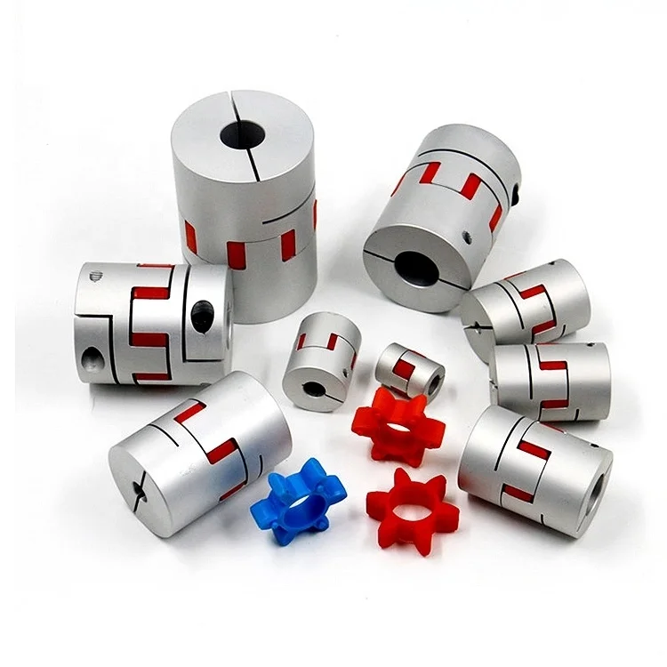
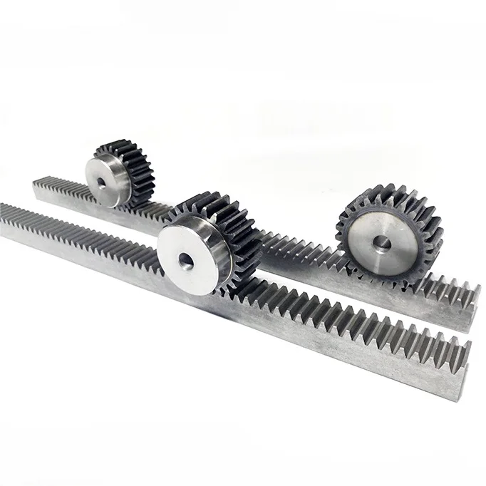
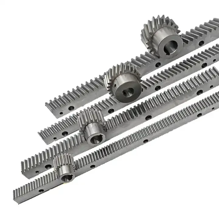
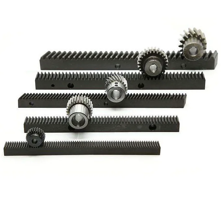
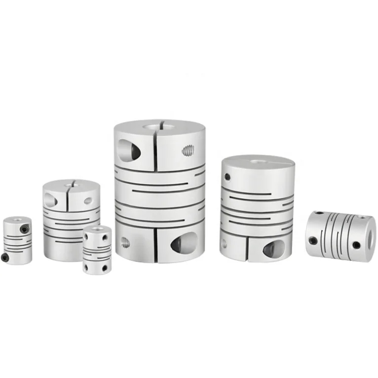
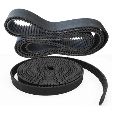
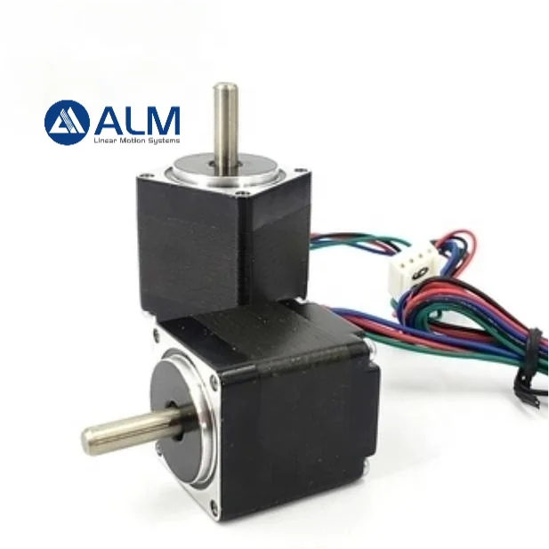
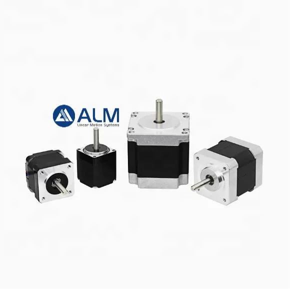
An axis is a chain: motor, coupling, transmission, screw or rack, carriage. Every element adds compliance, and the slowest one sets the bandwidth. This category holds the parts between the motor and the moving mass — the ones that are usually chosen last and blamed first.
What is here
| Item | Range | Where it fits |
|---|---|---|
| Gear rack and pinion | M1, M2, M3, M4, M5, M6 module; straight and helical | Long-travel axes where a rotating screw would whip: routers, plasma, laser |
| Flexible couplings | Jaw spider, helical slit, bellows | Motor to screw; absorbs small misalignment |
| Timing belts and pulleys | T and HTD profiles | Speed reduction or offset drive where a coupling will not reach |
| Stepper motors | NEMA 11, 17, 23, 24 hybrid | Open-loop positioning for light and medium axes |
Rack and pinion: module, not teeth count
The module is the pitch diameter in millimetres divided by the number of teeth, so an M2 pinion with 20 teeth has a 40 mm pitch diameter and travels 125.7 mm per revolution. Two racks with the same tooth count but different modules are not interchangeable, and a pinion must match the rack module exactly. For a long axis, the rack is supplied in sections and the joint between sections is where accuracy is lost — a poorly made joint shows up as a periodic error once per section length.
Helical teeth run more quietly and carry more load than straight teeth at the same module, at the cost of an axial thrust that has to be taken by a bearing.
Couplings: the compliance you want and the backlash you do not
A jaw coupling with a spider insert absorbs angular and parallel misalignment and damps shock. A helical slit coupling is stiffer and better for positioning. Both are zero-backlash when new; both develop play when the insert wears or the clamp screw loosens. On a reversing axis that play is lost motion, and no amount of tuning in the controller removes it.
The common installation error is to use the coupling to correct a large misalignment. It will work until the insert fails. Align the motor to the screw first, then fit the coupling.
Steppers, sized honestly
Stepper torque falls with speed. A motor with 3 N·m holding torque may deliver 0.3 N·m at 3,000 rpm on a 48 V drive, which is a tenth of the number on the label. Size on the torque at your working speed, not on holding torque, and expect the driver voltage to matter as much as the motor.
What to specify
- For rack: module, tooth count, rack length, straight or helical, and the pinion bore
- For couplings: bore on each side, outer diameter, torque, and allowable misalignment
- For belts: profile, pitch length, pulley teeth and bore
- For motors: frame size, step angle, current per phase, holding torque, and driver supply voltage